Technical characteristics type mh – Northern Connectors Harting DIN 41 612 Connectors User Manual
Page 156
04
.
20
DIN
P
ow
er
up t
o 1
5 A
Technical characteristics
Type MH
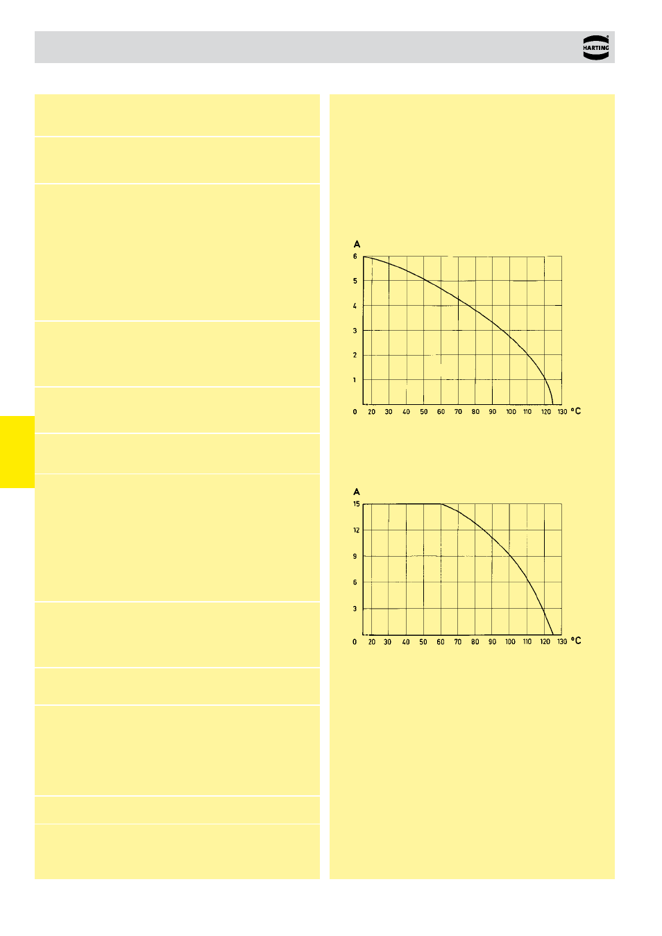
Current carrying capacity
The current carrying capacity is limited by maximum temperature of
materials for inserts and contacts including terminals. The current
capacity curve is valid for continuous, non interrupted current loaded
contacts of connectors when simultaneous power on all contacts is
given, without exceeding the maximum temperature.
Control and test procedures according to DIN IEC 60 512
W
or
king current
Ambient temperature
Electronic section
W
or
king current
Ambient temperature
Heavy duty section
* only for type MH 24 + 7
1)
Explanation of performance levels see chapter 00
Mating conditions
see chapter 00
Coding systems
see chapter 00
ELECTRONIC SECTION
Number of contacts
21, 24 + 7
HEAVY DUTY SECTION*
Number of contacts
7
Contact spacing (mm)
Male connector
2.54 x 5.08
Female connector
5.08
Working current
6 A max.
see current carrying capacity chart
Clearance
≥ 1.6 mm
Creepage
≥ 3 mm
Working voltage
The working voltage also depends on the
according to the safety regulations of the
clearance and creepage dimensions on the equipment. Explanations see chapter 00
pcb itself, and the associated wiring
Test voltage U
r.m.s.
1.55 kV
Contact resistance
≤
15 mΩ wrap, solder termination
≤
20 mΩ including crimp connection
Working current
15 A max.
see current carrying capacity chart
Clearance
≥ 4.5 mm
Creepage
≥ 8.0 mm
Working voltage
The working voltage also depends on the
according to the safety regulations of the
clearance and creepage dimensions on the equipment. Explanations see chapter 00
pcb itself, and the associated wiring
Test voltage U
r.m.s.
3.1 kV
Contact resistance
≤
8 mΩ
Electrical termination
Solder pins for pcb connection
Ø 1 ± 0.1 mm acc. to IEC 60 326-3
Wrap posts 1 x 1 mm
diagonal 1.34-1.45 mm
Crimp terminal 0.09-1.5 mm²
Electrical termination
Connector for faston 6.3 x 2.5
(faston width x wire gauge)
acc. to DIN 46 245 and DIN 46 247
Solder pins for pcb connection
Ø 1.6± 0.1 mm acc. to DIN EN 60097
Contact surface
Contact zone
Selectively plated according
to performance level
1)
Contact surface
Contact zone
Hard silver plated
BOTH PARTS
Insulation resistance
≥ 10
12
Ω for standard articles
≥ 10
11
Ω for special NFF articles
(with part-no. ending 222)
Temperature range
– 55 °C … + 125 °C
The higher temperature limit includes the local
ambient and heating effects of the contacts under load
Insertion and withdrawal force
≤ 85 N
Materials
Mouldings
Thermoplastic resin,
glass-fibre filled, UL 94-V0
Contacts
Copper alloy