Female connectors – Northern Connectors Harting DIN 41 612 Connectors User Manual
Page 52
01
.
26
64
64
64
64
64
64
64
64
64
c)
DIN
S
ig
na
l
up t
o 2 A
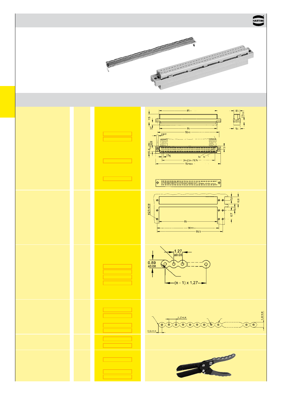
DIN 41 612 · Type C
Female connectors
Number of contacts
64
Number
Identification
of contacts
Part No.
Drawing
Dimensions in mm
Performance level 2
1)
Performance level 3
1)
Female connector
for insulation
displacement
Panel cut out
Cable 1 to contact 1 c
Mateable with 3 row male connector type C,
no female contacts in the middle row
Contact arrangement
View from termination side
Cable 1
Cable 1
Flat cable
AWG 28/7
grey
grey
colour coded
twisted pair
2)
Round flat cable
3)
with
screening
without
screening
Bench press
Base plate
Cable cutter
Spare parts
Blade
Cutting plate
2)
Termination area
spacing = 508 mm
Important: always
store reels vertically
Wire (tinned)
Cu
Gauge
AWG 28/7 0.089 mm²
Insulation material as per UL style PVC
Further components and accessories for insulation displacement see interface catalogue, chapter 40
c)
Connectors with coding see chapter 00
1)
acc. to IEC 60 603-2
3)
Termination area
spacing = 100 mm
Strain relief (metal)
grey
Edge mark
on first conductor
Edge mark on
first conductor
AWG 28/7
grey
30.48 m
100.00 m
30.48 m
)
30.48 m
30.48 m
100.00 m
30.48 m
100.00 m
- Hummel M40 Circular Power Connectors (20 pages)
- Hummel M27 Circular Connectors (10 pages)
- Hummel M23-Signal - Circular Connectors (32 pages)
- Hummel M23-Power - Circular Connectors (24 pages)
- Hummel M23 RJ45 Circular Connectors (10 pages)
- Hummel M23 Fast Ethernet PoE Circular Connectors (12 pages)
- Hummel M16 Circular Connectors (26 pages)
- Hummel M16 Stainless Steel Connector Housings (10 pages)
- Hirschmann NR-Series Circular Connectors (23 pages)
- Hirschmann CM-Series Plastic Screw Locking Connectors (MIL-C-5015) (11 pages)
- Hirschmann CA-Series Plastic Screw Locking Circular Connectors (2 pages)
- Normek PCB Connectors (2 pages)
- Harting Har-flexicon Connectors (34 pages)
- Harting Har-flex PCB Connectors (17 pages)
- Harting D-sub Connectors, Housings & Accessories (203 pages)
- D-Sub Plastic Hoods (10 pages)
- D-Sub Metalized Plastic Hoods (8 pages)
- D-Sub Full Metal Hoods (22 pages)
- Conec D-Sub Hoods & Accessories (54 pages)
- Lumberg Automation M12 Single-Ended Cordsets (2 pages)
- Lumberg Automation M12 Field-Attachable Cable Connectors (2 pages)
- Mennekes Plugs - IP67 (1 page)
- Mennekes Wall Mounted Inlet (1 page)
- Souriau UT0 Metal Circular Connectors (12 pages)
- Souriau UT0W Metal High Density Circular Connectors (12 pages)
- Souriau UTG Plastic Circular Connectors with Metal Coupling (32 pages)
- Souriau UTL Series Push-Pull Connectors (60 pages)
- Souriau UTP Plastic Circular Connectors (24 pages)
- Souriau UTS Hi Seal Plastic Circular Waterproof Connectors (8 pages)
- Souriau UTS Screw Termination' Plastic Circular Waterproof Connectors (4 pages)
- Souriau UTS Plastic Circular Waterproof Connectors (5 pages)
- Souriau 840 Series Metal Circular Connectors (10 pages)
- Souriau MBG Plastic Circular Connectors (24 pages)
- Souriau Mixed Power / Signal Circular Connectors (5 pages)
- Souriau Overmoulded Cable Assemblies (8 pages)
- Souriau VGE1 / FER1 Ruggedized Metal MIL-DTL-5015 & VG 95234 Connectors (1 page)
- Souriau VGE1 / FER1 Ruggedized Metal MIL-DTL-5015 & VG 95234 Connectors (31 pages)
- Mennekes Panel Mounted Sockets (5 pages)
- Mennekes Panel Mounted Inlet (1 page)
- Mennekes Connectors - IP67 (1 page)
- Mennekes Connectors - IP44 (1 page)
- Lumberg Automation M8 Single-Ended Cordsets (2 pages)
- Alpha Wire XTRA-GUARD Performance Cable (94 pages)
- Alpha Wire Hook-Up Wire (48 pages)
- Alpha Wire FIT Heat-Shrink Tubing (34 pages)