Type 2f connectors, Max . 24, Interface connector i – Northern Connectors Harting DIN 41 612 Connectors User Manual
Page 144
03
.
44
24
1
2
3
2
3
1
2
3
FC 1
FC 2
FC 3
DIN
P
ow
er
up t
o 6 A
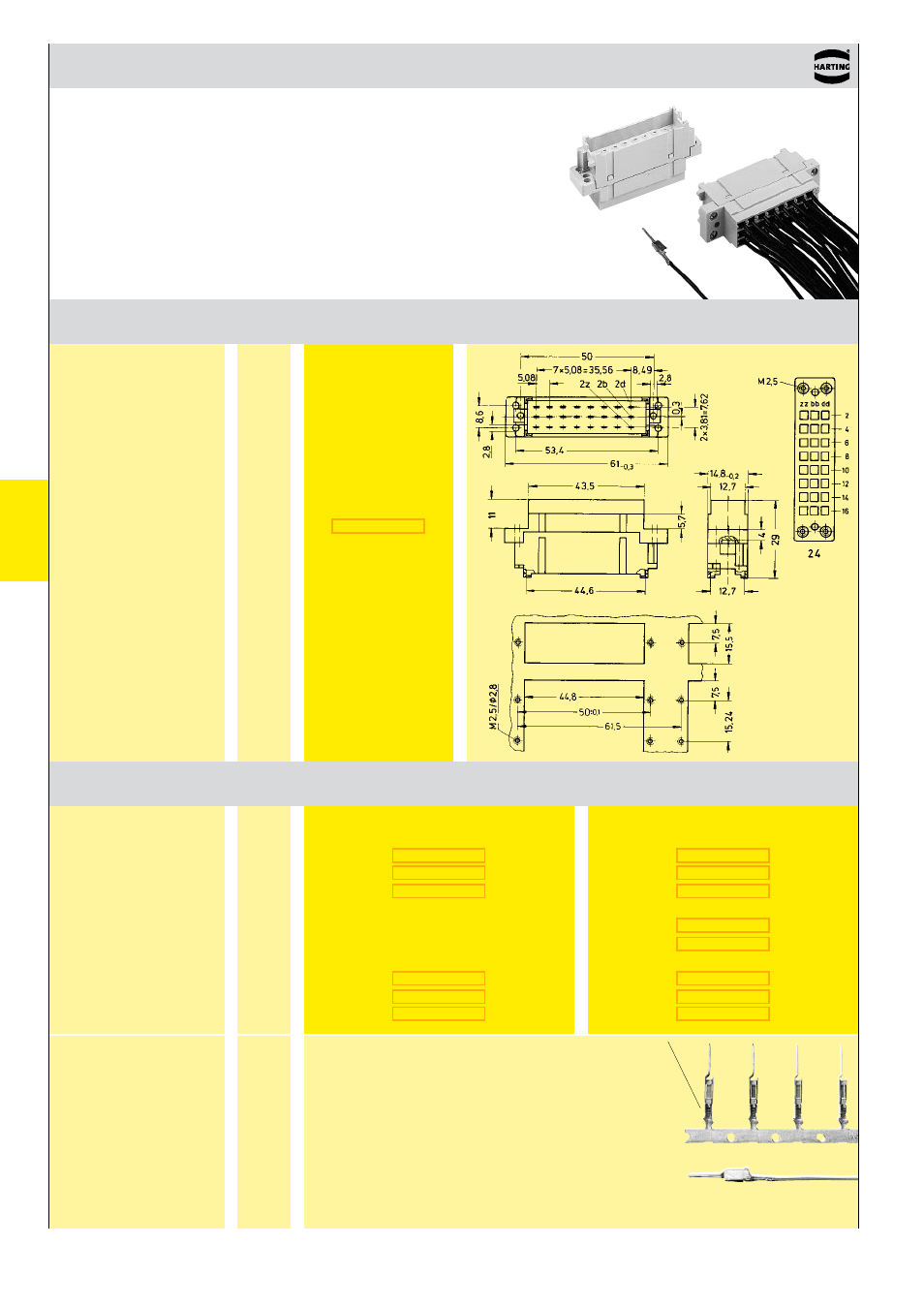
DIN 41 612 · complementary type 2F
Interface connector I
Number of contacts
max . 24
Number
Identification
of contacts
Part No .
Drawing
Dimensions in mm
Interface connector I
for male crimp contacts
Order contacts separately
Male crimp FC
contacts
Bandoliered contacts
(approx . 2,500 pieces)
Bandoliered contacts
(approx . 250 pieces)
Individual contacts
1)
Wire gauge
Insulation ø
mm²
AWG mm
Identification
Identification
Wire gauge
Part No . Performance levels according to IEC 60603-2 . Explanation chapter 00
2
1
Identification
Bandoliered
contacts
Individual contacts
1)
Packaging unit 1,000 pieces
3 .5 + 0 .5 mm of insulation is stripped from the wires
to be crimped
For the fabrication in line with the specification please
use exclusively crimp tools approved by HARTING
(see DIN EN 60 352-2)
Insertion, removal and crimping tools see chapter 30
1
0 .09 - 0 .25
28 - 24
0 .7 - 1 .5
2
0 .14 - 0 .56
26 - 20
0 .8 - 2 .0
3
0 .5 - 1 .5
20 - 16
1 .6 - 2 .8
- Hummel M40 Circular Power Connectors (20 pages)
- Hummel M27 Circular Connectors (10 pages)
- Hummel M23-Signal - Circular Connectors (32 pages)
- Hummel M23-Power - Circular Connectors (24 pages)
- Hummel M23 RJ45 Circular Connectors (10 pages)
- Hummel M23 Fast Ethernet PoE Circular Connectors (12 pages)
- Hummel M16 Circular Connectors (26 pages)
- Hummel M16 Stainless Steel Connector Housings (10 pages)
- Hirschmann NR-Series Circular Connectors (23 pages)
- Hirschmann CM-Series Plastic Screw Locking Connectors (MIL-C-5015) (11 pages)
- Hirschmann CA-Series Plastic Screw Locking Circular Connectors (2 pages)
- Normek PCB Connectors (2 pages)
- Harting Har-flexicon Connectors (34 pages)
- Harting Har-flex PCB Connectors (17 pages)
- Harting D-sub Connectors, Housings & Accessories (203 pages)
- D-Sub Plastic Hoods (10 pages)
- D-Sub Metalized Plastic Hoods (8 pages)
- D-Sub Full Metal Hoods (22 pages)
- Conec D-Sub Hoods & Accessories (54 pages)
- Lumberg Automation M12 Single-Ended Cordsets (2 pages)
- Lumberg Automation M12 Field-Attachable Cable Connectors (2 pages)
- Mennekes Plugs - IP67 (1 page)
- Mennekes Wall Mounted Inlet (1 page)
- Souriau UT0 Metal Circular Connectors (12 pages)
- Souriau UT0W Metal High Density Circular Connectors (12 pages)
- Souriau UTG Plastic Circular Connectors with Metal Coupling (32 pages)
- Souriau UTL Series Push-Pull Connectors (60 pages)
- Souriau UTP Plastic Circular Connectors (24 pages)
- Souriau UTS Hi Seal Plastic Circular Waterproof Connectors (8 pages)
- Souriau UTS Screw Termination' Plastic Circular Waterproof Connectors (4 pages)
- Souriau UTS Plastic Circular Waterproof Connectors (5 pages)
- Souriau 840 Series Metal Circular Connectors (10 pages)
- Souriau MBG Plastic Circular Connectors (24 pages)
- Souriau Mixed Power / Signal Circular Connectors (5 pages)
- Souriau Overmoulded Cable Assemblies (8 pages)
- Souriau VGE1 / FER1 Ruggedized Metal MIL-DTL-5015 & VG 95234 Connectors (1 page)
- Souriau VGE1 / FER1 Ruggedized Metal MIL-DTL-5015 & VG 95234 Connectors (31 pages)
- Mennekes Panel Mounted Sockets (5 pages)
- Mennekes Panel Mounted Inlet (1 page)
- Mennekes Connectors - IP67 (1 page)
- Mennekes Connectors - IP44 (1 page)
- Lumberg Automation M8 Single-Ended Cordsets (2 pages)
- Alpha Wire XTRA-GUARD Performance Cable (94 pages)
- Alpha Wire Hook-Up Wire (48 pages)
- Alpha Wire FIT Heat-Shrink Tubing (34 pages)