Northern Connectors Harting DIN 41 612 Connectors User Manual
Page 22
00
.
16
Gen
er
al
in
fo
rma
tio
n
DIN 41 612 · Coding systems
Identification
Part No.
Drawing
Dimensions in mm
Coding system
with contact loss
Coding system
without contact loss
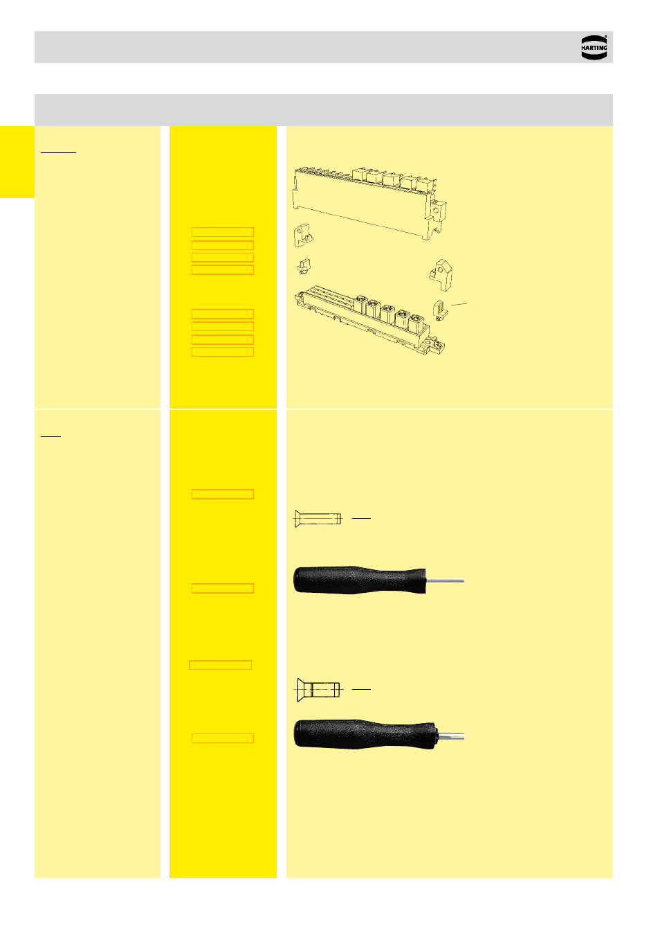
To avoid accidental and incorrect mating of adjacent connectors a coding system
is required. The coding is achieved by means of a code pin which is inserted into
the selected chamber of the female connector (the contact cavity must be filled
with a female contact!).
The opposite male contact must be removed with the help of the specially
designed tool.
It’s recommended to use a number of code pins in relation to the total number of
contacts per connector: 3 pins for 64 contacts, 7 pins for 160 contacts.
Code pin for types
D, E, F, FM, 2F, MH
Removal tool
for
male contacts
Plastic, grey
Code keys
for male connectors
flange coding
Type MH 21 + 5
colour red
blue
green
orange
for female connectors
colour red
blue
green
orange
can be mounted
with a screwdriver
(max. width 3 mm)
Code pin for types
B, 2B, 3B,
C, 2C, 3C,
M, M-flat,
Q, 2Q,
R, R (HE 11), 2R,
har-bus 64
Removal tool
for
male contacts
Plastic, black
- Hummel M40 Circular Power Connectors (20 pages)
- Hummel M27 Circular Connectors (10 pages)
- Hummel M23-Signal - Circular Connectors (32 pages)
- Hummel M23-Power - Circular Connectors (24 pages)
- Hummel M23 RJ45 Circular Connectors (10 pages)
- Hummel M23 Fast Ethernet PoE Circular Connectors (12 pages)
- Hummel M16 Circular Connectors (26 pages)
- Hummel M16 Stainless Steel Connector Housings (10 pages)
- Hirschmann NR-Series Circular Connectors (23 pages)
- Hirschmann CM-Series Plastic Screw Locking Connectors (MIL-C-5015) (11 pages)
- Hirschmann CA-Series Plastic Screw Locking Circular Connectors (2 pages)
- Normek PCB Connectors (2 pages)
- Harting Har-flexicon Connectors (34 pages)
- Harting Har-flex PCB Connectors (17 pages)
- Harting D-sub Connectors, Housings & Accessories (203 pages)
- D-Sub Plastic Hoods (10 pages)
- D-Sub Metalized Plastic Hoods (8 pages)
- D-Sub Full Metal Hoods (22 pages)
- Conec D-Sub Hoods & Accessories (54 pages)
- Lumberg Automation M12 Single-Ended Cordsets (2 pages)
- Lumberg Automation M12 Field-Attachable Cable Connectors (2 pages)
- Mennekes Plugs - IP67 (1 page)
- Mennekes Wall Mounted Inlet (1 page)
- Souriau UT0 Metal Circular Connectors (12 pages)
- Souriau UT0W Metal High Density Circular Connectors (12 pages)
- Souriau UTG Plastic Circular Connectors with Metal Coupling (32 pages)
- Souriau UTL Series Push-Pull Connectors (60 pages)
- Souriau UTP Plastic Circular Connectors (24 pages)
- Souriau UTS Hi Seal Plastic Circular Waterproof Connectors (8 pages)
- Souriau UTS Screw Termination' Plastic Circular Waterproof Connectors (4 pages)
- Souriau UTS Plastic Circular Waterproof Connectors (5 pages)
- Souriau 840 Series Metal Circular Connectors (10 pages)
- Souriau MBG Plastic Circular Connectors (24 pages)
- Souriau Mixed Power / Signal Circular Connectors (5 pages)
- Souriau Overmoulded Cable Assemblies (8 pages)
- Souriau VGE1 / FER1 Ruggedized Metal MIL-DTL-5015 & VG 95234 Connectors (1 page)
- Souriau VGE1 / FER1 Ruggedized Metal MIL-DTL-5015 & VG 95234 Connectors (31 pages)
- Mennekes Panel Mounted Sockets (5 pages)
- Mennekes Panel Mounted Inlet (1 page)
- Mennekes Connectors - IP67 (1 page)
- Mennekes Connectors - IP44 (1 page)
- Lumberg Automation M8 Single-Ended Cordsets (2 pages)
- Alpha Wire XTRA-GUARD Performance Cable (94 pages)
- Alpha Wire Hook-Up Wire (48 pages)
- Alpha Wire FIT Heat-Shrink Tubing (34 pages)