Technical characteristics – Northern Connectors Harting DIN 41 612 Connectors User Manual
Page 36
01
.
10
DIN
S
ig
na
l
up t
o 2 A
Technical characteristics
Types B, 2B, 3B, C, 2C, 3C, M, M invers,
Q, 2Q, 3Q, R, R (HE 11), 2R, 3R
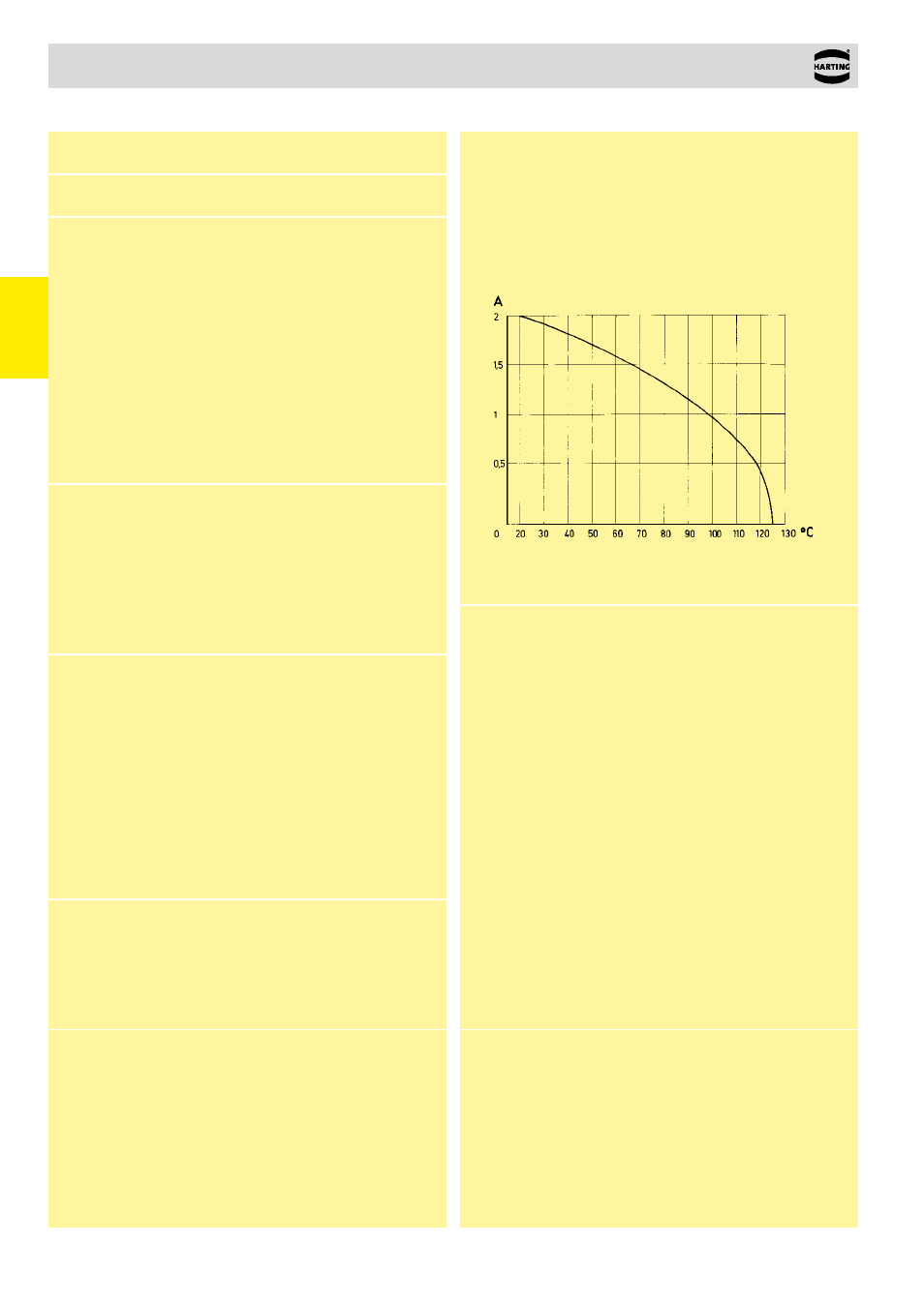
Current carrying capacity
The current carrying capacity is limited by maximum temperature of
materials for inserts and contacts including terminals. The current
capacity curve is valid for continuous, non interrupted current loaded
contacts of connectors when simultaneous power on all contacts is
given, without exceeding the maximum temperature.
Control and test procedures according to DIN IEC 60 512
W
or
king current
Ambient temperature
Pin shroud for male and female connectors
with 0.6 x 0.6 mm pins
A secure interfacing system for signals from the rear of 19” racks
to connectors with wrap posts 0.6 x 0.6 mm is possible with the
use of a pin shroud.
The pin shroud protects the wrap posts on the rear side of the rack
and can be screwed to the printed circuit board (screw fixing) or
can be pressed onto the pins (press-in fixing).
After assembly the rear ends of the wire wrap posts become the
mating areas of a type C resp. type 2C male connector.
This system can now accept:
●
female connectors type C
●
female connectors type 2C
●
female connectors type R
●
female connectors type 2R
The locking levers provide security for the mated connectors. Fast
and simple disconnection is possible (see application examples,
pages 01.64 ff).
Fitting and removing crimp contacts
see technical characteristics chapter 03
Number of contacts
16-96
Contact spacing (mm)
2.54
Working current
2 A max.
see current carrying
1 A with insulation displacement
capacity chart
40 A max. type M
Clearance
≥ 1.2 mm
Creepage
≥ 1.2 mm
Working voltage
The working voltage also depends according to the safety regulations
on the clearance and creepage
of the equipment
dimensions of the pcb itself,
Explanations see chapter 00
and the associated wiring
Test voltage U
r.m.s.
1 kV
Contact resistance
≤ 20 mΩ
Insulation resistance
≥ 10
12
Ω for standard articles
≥ 10
11
Ω for special NFF articles
(with part-no. ending 222)
Temperature range
– 55 °C … + 125 °C
The higher temperature limit
– 40 °C … + 105 °C
includes the local ambient
for press-in connector
and heating effects of the
contacts under load
During reflow soldering
max. + 240 °C for 15 s
for SMC connectors
Degree of protection for crimp terminal
IP 20
according to DIN 40 050
Electrical termination
Male and female connector
Solder pins for pcb connections
Ø 1.0 ± 0.1 mm
according to IEC 60 326-3
wrap posts 0.6 x 0.6 mm
diagonal 0.79-0.86 mm
Crimp terminal 0.09-0.5 mm²
Insulation displacement
connection AWG 28/7
Compliant press-in
terminations
PCB thickness
≥ 1.6 mm
Recommended PCB holes
See recommendation page 00.25
for press-in technology
in acc. to EN 60 352-5
Insertion and withdrawal force
16way ≤ 15 N
20way
≤ 20 N
30way
≤ 30 N
32way
≤ 30 N
48way
≤ 45 N
64way
≤ 60 N
96way
≤ 90 N
Materials
Mouldings
Thermoplastic resin,
glass-fibre filled, UL 94-V0
Contacts
Copper alloy
Contact surface
Contact zone
Selectively plated according to
performance level
1)
1)
Explanation performance levels see chapter 00
Mating conditions see chapter 00