Specifications, assembly instructions – Northern Connectors Harting DIN 41 612 Connectors User Manual
Page 12
00
.
06
➀ + ➂
➁
Gen
er
al
in
fo
rma
tio
n
Specifications, assembly instructions
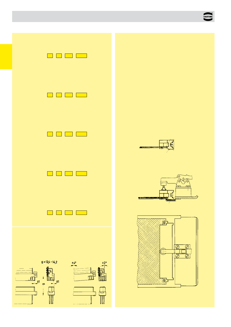
Soldering the male connectors into pcb´s
Male connectors should be protected when being soldered in a dip,
flow or film soldering baths. Otherwise, they might become contami-
nated as a result of soldering operations or deformed as a result of
overheating.
➀
For prototypes and short runs protect the connectors with an
indus
trial adhesive tape, e.g. Tesaband 4331 (www.tesa.de).
Cover the underside of the connector moulding and the adjacent
parts of the pcb as well as the open sides of the connector. This will
prevent heat and gases of the soldering apparatus from damaging
the connector. About 140 + 5 mm of the tape should suffice.
➁
For large series a jig is recommended. Its protective cover with
a fast action mechanical locking device shields the connectors
from gas and heat generated by the sol dering apparatus. As an
additional protection a foil can be used for cov ering the parts that
should not be soldered.
➂
For prototypes and short runs the protection described under
point
➀
can be replaced by a solder protection cap. This cap can
be ordered under the part no. 09 02 000 9935.
Performance level 3 as per IEC 60 603-2
50 mating cycles
then visual inspection.
No gas test.
No functional impairment.
Part No. explanation
09
. .
. . .
7 . . .
Performance level 2 as per IEC 60 603-2
400 mating cycles.
200 mating cycles
then 4 days gas test using 10 ppm SO
2
.
Measurement of contact resistance.
200 mating cycles
then visual inspection. No abrasion of the
contact finish through to the base material.
No functional impairment.
Part No. explanation
09
. .
. . .
6 . . .
Performance level 1 as per IEC 60 603-2
500 mating cycles.
250 mating cycles
then 10 days gas test using 10 ppm SO
2
.
Measurement of contact resistance.
250 mating cycles
then visual inspection. No abrasion of the
contact finish through to the base material.
No functional impairment.
Part No. explanation
09
. .
. . .
2 . . .
Performance level 2 as per IEC 61 076-4-113
250 mating cycles.
125 mating cycles
then 4 days gas test using 10 ppm SO
2
.
Measurement of contact resistance.
125 mating cycles
then visual inspection. No abrasion of the
contact finish through to the base material.
No functional impairment.
Part No. explanation
02
. .
. . .
2 . . .
Performance level 1 as per IEC 61 076-4-113
500 mating cycles.
250 mating cycles
then 10 days gas test using 10 ppm SO
2
.
Measurement of contact resistance.
250 mating cycles
then visual inspection. No abrasion of the
contact finish through to the base material.
No functional impairment.
Part No. explanation
02
. .
. . .
1 . . .
Other plating finishes available on request.
Mating conditions
To ensure reliable connections and prevent unnecessary damage,
please refer to the application data diagrams.
These recommendations are set out in IEC 60 603-2.
The connectors should not be coupled and decoupled under electrical
load.
Adhesive tape or
protection cap
Intermediate foil