Female connectors – Northern Connectors Harting DIN 41 612 Connectors User Manual
Page 68
01
.
42
78 + 2
60 + 4
42 + 6
24 + 8
78 + 2
f)
60 + 4
42 + 6
24 + 8
f)
78 + 2
60 + 4
42 + 6
24 + 8
Y
DIN
S
ig
na
l
up t
o 2 A
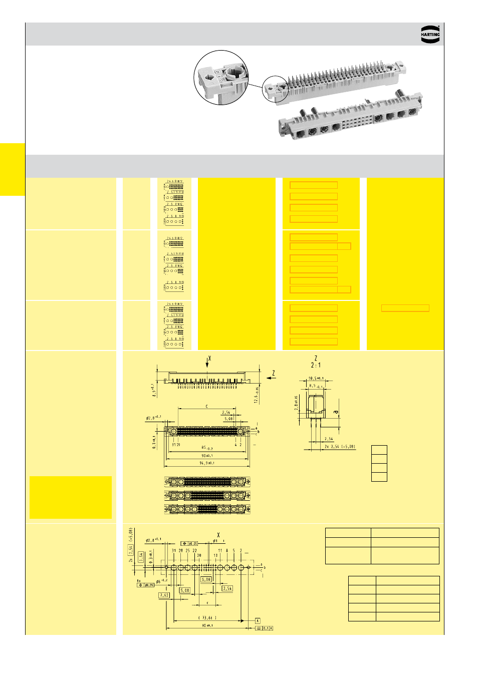
DIN 41 612 · Type M
Female connectors
Number of contacts
78+2, 60+4,
42+6, 24+8
Female connector
with solder pins
2.9 mm
(without special contacts)
Dimensions
Board drillings
Mounting side
Dimensions in mm
Order high current,
high voltage, coaxial
and fibre optic contacts
separately, see pages
01.38 ff
Type
position
all holes
row
position
row
Other contact arrangements on request
f)
Railway classification NFF 16-101, Smoke index: F1, Flammability class: I2
Number Contact
Identification
of contacts arrangement
Part No. Performance levels according to IEC 60603-2. Explanation chapter 00
3 2 1
Board drillings depend on
type and special contact
loading
c
78 + 2 25 x 2.54 = 63.5
0
60 + 4 19 x 2.54 = 48.26
42 + 6 13 x 2.54 = 33.02
24 + 8 7 x 2.54 = 17.78
Female connector
with solder pins
4.5 mm
(without special contacts)
Female connector
with press-in pins
4.5 mm
(without special contacts)
Press-in pins
Solder pins
a
2.9
4.5
4.5
Performance level 3
on request
Y
Solder
1 ± 0.1
Press-in
see recommendation
page 00.25
- Hummel M40 Circular Power Connectors (20 pages)
- Hummel M27 Circular Connectors (10 pages)
- Hummel M23-Signal - Circular Connectors (32 pages)
- Hummel M23-Power - Circular Connectors (24 pages)
- Hummel M23 RJ45 Circular Connectors (10 pages)
- Hummel M23 Fast Ethernet PoE Circular Connectors (12 pages)
- Hummel M16 Circular Connectors (26 pages)
- Hummel M16 Stainless Steel Connector Housings (10 pages)
- Hirschmann NR-Series Circular Connectors (23 pages)
- Hirschmann CM-Series Plastic Screw Locking Connectors (MIL-C-5015) (11 pages)
- Hirschmann CA-Series Plastic Screw Locking Circular Connectors (2 pages)
- Normek PCB Connectors (2 pages)
- Harting Har-flexicon Connectors (34 pages)
- Harting Har-flex PCB Connectors (17 pages)
- Harting D-sub Connectors, Housings & Accessories (203 pages)
- D-Sub Plastic Hoods (10 pages)
- D-Sub Metalized Plastic Hoods (8 pages)
- D-Sub Full Metal Hoods (22 pages)
- Conec D-Sub Hoods & Accessories (54 pages)
- Lumberg Automation M12 Single-Ended Cordsets (2 pages)
- Lumberg Automation M12 Field-Attachable Cable Connectors (2 pages)
- Mennekes Plugs - IP67 (1 page)
- Mennekes Wall Mounted Inlet (1 page)
- Souriau UT0 Metal Circular Connectors (12 pages)
- Souriau UT0W Metal High Density Circular Connectors (12 pages)
- Souriau UTG Plastic Circular Connectors with Metal Coupling (32 pages)
- Souriau UTL Series Push-Pull Connectors (60 pages)
- Souriau UTP Plastic Circular Connectors (24 pages)
- Souriau UTS Hi Seal Plastic Circular Waterproof Connectors (8 pages)
- Souriau UTS Screw Termination' Plastic Circular Waterproof Connectors (4 pages)
- Souriau UTS Plastic Circular Waterproof Connectors (5 pages)
- Souriau 840 Series Metal Circular Connectors (10 pages)
- Souriau MBG Plastic Circular Connectors (24 pages)
- Souriau Mixed Power / Signal Circular Connectors (5 pages)
- Souriau Overmoulded Cable Assemblies (8 pages)
- Souriau VGE1 / FER1 Ruggedized Metal MIL-DTL-5015 & VG 95234 Connectors (1 page)
- Souriau VGE1 / FER1 Ruggedized Metal MIL-DTL-5015 & VG 95234 Connectors (31 pages)
- Mennekes Panel Mounted Sockets (5 pages)
- Mennekes Panel Mounted Inlet (1 page)
- Mennekes Connectors - IP67 (1 page)
- Mennekes Connectors - IP44 (1 page)
- Lumberg Automation M8 Single-Ended Cordsets (2 pages)
- Alpha Wire XTRA-GUARD Performance Cable (94 pages)
- Alpha Wire Hook-Up Wire (48 pages)
- Alpha Wire FIT Heat-Shrink Tubing (34 pages)