Forced ventilated or naturally ventilated motors, Ȧȧ ȡ ȣ, Ȧȧ ȣ ȥ – Lenze EVS9332xS User Manual
Page 29: Safety instructions, X t monitoring
Safety instructions
Thermal motor monitoring
Forced ventilated or naturally ventilated motors
2.2
2.2.1
l
2.2−2
EDSVS9332S EN 6.0−07/2013
2.2.1
Forced ventilated or naturally ventilated motors
The following codes can be set for I
2
x t monitoring:
Code
Meaning
Value range
Lenze setting
C0066
Display of the I
2
x t load of the motor
0 ... 250 %
−
C0120
Threshold: Triggering of error "OC6"
0 ... 120 %
0 %
C0127
Threshold: Triggering of error "OC8"
0 ... 120 %
0 %
C0128
Thermal motor time constant
0.1 ... 50.0 min
5.0 min
C0606
Response to error "OC8"
TRIP, warning, off
Warning
Formula for release time
Information
t
+ * ( t ) ln
ȧȧ
ȡ
Ȣ
1
*
z
) 1
ǒ
IMot
IN
Ǔ
2
100
ȧȧ
ȣ
Ȥ
I
Mot
Actual motor current (C0054)
I
r
Rated motor current (C0088)
t
Thermal motor time constant (C0128)
z
Threshold value in C0120 (OC6) or
C0127 (OC8)
Formulae for I
2
x t load
Information
L(t)
+
ǒ
I
Mot
I
N
Ǔ
2
100%
ǒ
1
* e
*t
t
Ǔ
L(t)
Chronological sequence of the I
2
x t
load of the motor
(Display: C0066)
I
Mot
Actual motor current (C0054)
Ir
Rated motor current (C0088)
t
Thermal motor time constant (C0128)
If the controller is inhibited, the I
2
x t load is reduced:
L(t)
+ L
Start
e
* tt
Ǹ
L
Start
I
2
x t load before controller inhibit
If an error is triggered, the value
corresponds to the threshold value set
in C0120 (OC6) or C0127 (OC8).
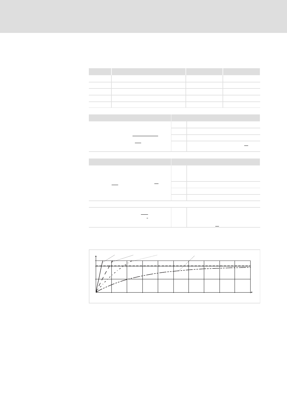
Diagram for detecting the release times for a motor with a thermal motor
time constant of 5 minutes (Lenze setting C0128):
I
= 3 × I
Mot
N
0
50
100
120
0
100
200
300
400
500
600
700
800
900
1000
t [s]
L [%]
I
= 2 × I
Mot
N
I
= 1.5 × I
Mot
N
I
= 1 × I
Mot
N
9300STD105
Fig. 2.2−1
I
2
× t−monitoring: Release times for different motor currents and trigger
thresholds
I
Mot
Actual motor current (C0054)
I
r
Rated motor current (C0088)
L
I
2
x t load of the motor (display: C0066)
T
Time
Parameter setting
Calculate release time and
I
2
xt load
Read release time in the
diagram