Motor connection, Wiring of the standard device, Stop – Lenze EVS9332xS User Manual
Page 114: Danger
Wiring of the standard device
Standard devices in the power range 15 ... 30 kW
Motor connection
5.5
5.5.6
l
5.5−7
EDSVS9332S EN 6.0−07/2013
5.5.6
Motor connection
)
Note!
ƒ
Fusing the motor cable is not required.
ƒ
The drive controller features 2 connections for motor
temperature monitoring:
– Terminals T1, T2 for connecting a PTC thermistor or thermal
contact (NC contact).
– Pins X8/5 and X8/8 of the incremental encoder input (X8) for
connecting a KTY thermal sensor.
(
Stop!
Do not use lugs as strain relief.
PE
T1
T2
U
V
W
a
3.4 Nm
30 lb-in
a
0
9300vec131
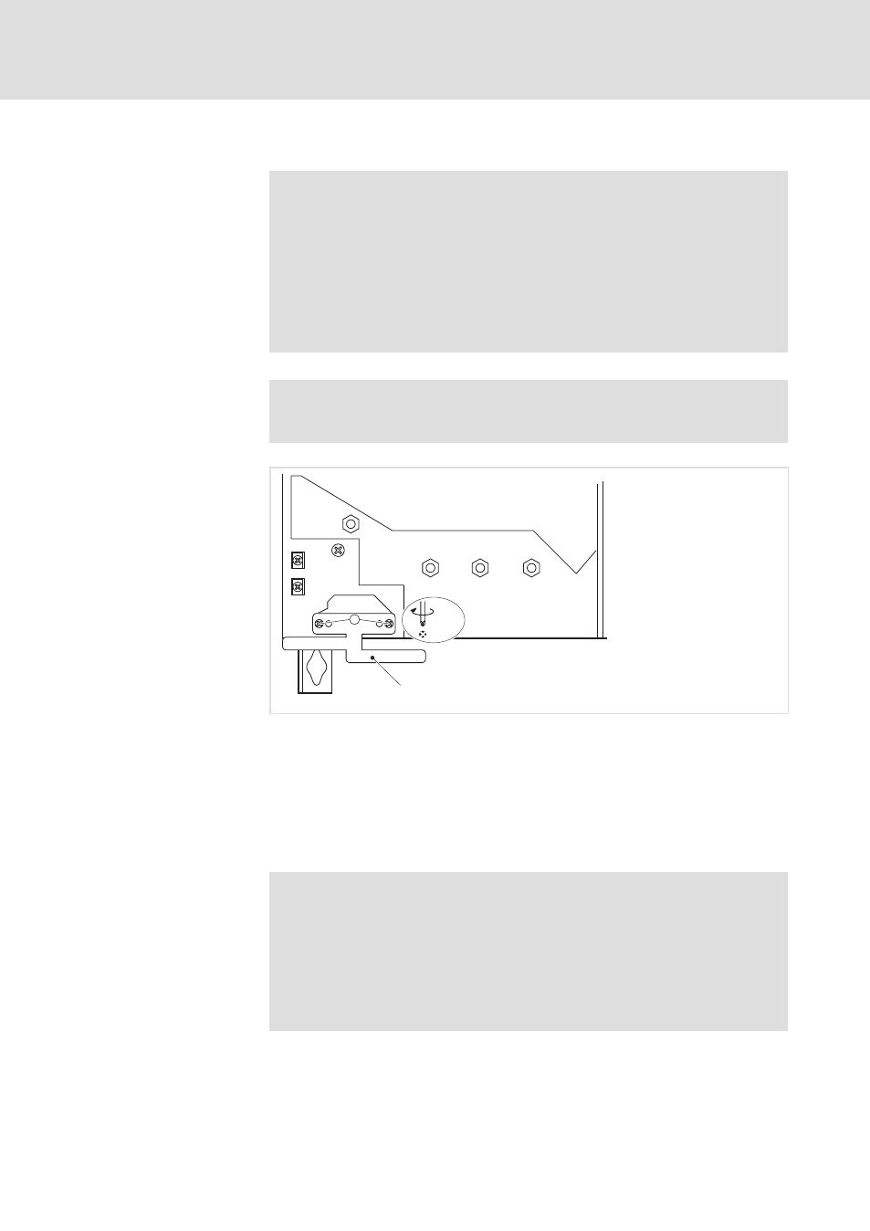
Fig. 5.5−3
Installation of shield sheet for drive controllers 15 ... 30 kW
0 Fasten the shield sheet with two self−tapping screws Ж 4 Ч 14 mm (a)
Wire T1, T2 only if the motor is equipped with a PTC thermistor or thermal
contact (NC contact).
ƒ An "open" cable acts like an antenna and can cause faults on the drive
controller.
{
Danger!
ƒ
All control terminals only have basic insulation (single
isolating distance) after connecting a PTC thermistor or a
thermal contact.
ƒ
Protection against accidental contact in case of a defective
isolating distance is only guaranteed through external
measures, e.g. double insulation.
Shield sheet installation
Motor with PTC thermistor or
thermal contact (NC contact)