Load for linear drives and piston rod cylinders – Festo Контроллер позиционирования CPX-CMAX User Manual
Page 43
2. Fitting and pneumatic installation
2−13
Festo P.BE−CPX−CMA X−SYS−EN en 0908NH
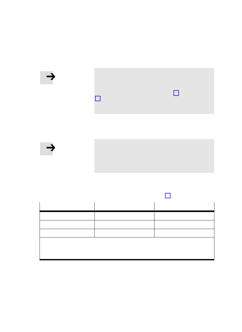
Note
Minimum load.
A pneumatic positioning axis always requires a minimum
load. You can find these values in tables Tab. 2/4 and
Tab. 2/6.
If necessary, this minimum load must be ensured through
the use of an additional weight.
For every positioning job, you have the option of specifying
the respectively existing load, thereby adjusting the conĆ
troller setting of the CMAX to the various loads.
Note
If the load varies from positioning job to positioning job
(e.g. due to changing workpieces) by more than 30%, the
load in the positioning job must be adjusted to the actual
parameters.
Load for linear drives and piston rod cylinders
Determine the permissible load using Tab. 2/4:
Mounting position
Maximum load
Minimum load
horizontal (
á = 0°)
m
max
0.1 * m
max
vertical (
á = 90°)
0.33 * m
max
0.1 * m
max
diagonal (0°
< á < 90°)
(1 ć 2/3 sin
á) * m
max
0.1 * m
max
á
= mounting position in [°]
m
max
= d³ * p
sys
* 0.008 (maximum load for horizontal mounting position [kg] )
d
= cylinder diameter [mm]
p
sys
= supply pressure [bar]
Tab. 2/4: Maximum and minimum load
Example:
Load for DNCI−32 with p = 6 bar.