Using the front panel, Chapter 4, Overview – ADTRAN Atlas 550 User Manual
Page 51: Aco switch
61200305L1-1
ATLAS 550 User Manual
4-1
Chapter 4
Using the Front Panel
OVERVIEW
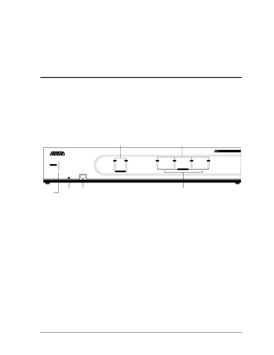
The front panel contains the Alarm Cut-off (ACO) switch, the CRAFT port,
and the controller and module status LEDs. The LEDs provide visual infor-
mation about the ATLAS 550 Base Unit and any option module that may be
installed. Figure 4-1 identifies the ACO switch, the CRAFT port, and the
LEDs.
Figure 4-1. ATLAS 550 Front Panel Layout
ACO SWITCH
The ACO switch deactivates (clears) the Alarm Relay, located on the rear
panel of the ATLAS 550, after an alarm condition has occurred. If an alarm
condition is corrected and then reoccurs, the Alarm Relay will re-energize
(see also ACO Switch in Table 4-2 on page 4-3).
POWER
REMOTE
ERROR
TEST
OK
TEST
ONLINE
STATUS
ERROR
TEST
OK
CRAFT
ACO
ALARM
ALARM
1
2
NETWORK
1
2
3
4
MODULES
SYSTEM
ETHERNET
ATLAS 550
Module Status LEDs
CRAFT
Port
Alarm
Cut-off
Switch
Controller
Status
LEDs
Network Module
Status LEDs
Option Module
Slot Numbers
- Express 4110 (205 pages)
- Gigabit Ethernet Multi-Mode Fiber Tributary Module 1184519L1 (2 pages)
- U-BR1TE ISDN 2B1Q (4 pages)
- DSU/CSU (6 pages)
- 3010 (30 pages)
- NetVanta 1024 (2 pages)
- FT1 (10 pages)
- IP Mini-DSLAM (2 pages)
- 6530 (20 pages)
- 6530 (2 pages)
- AHT1U (2 pages)
- DS3 MX (2 pages)
- 600R (264 pages)
- DUAL Nx56/64 1200142L1# (42 pages)
- NetVanta T1/FT1 + DSX-1 (2 pages)
- IQ SERIES 56 (1 page)
- 1200070L2 (187 pages)
- 1200051L2 (165 pages)
- NETVANTA 3120 (2 pages)
- 1200 (2 pages)
- NetVanta Series (2 pages)
- 850 (4 pages)
- ATLAS 800 Series Module QUAD E1 (2 pages)
- Atlas 830 (2 pages)
- TSU LT (2 pages)
- Express L1.5 (2 pages)
- MX2820-48 VDC M13 MUX (2 pages)
- Dial Backup Interface Module 1204006L2 (2 pages)
- 900 Series (2 pages)
- Atlas 550 (1 page)
- NetVanta 5305 (2 pages)
- 1200350L1 (134 pages)
- ATM Mini-DSLAM (2 pages)
- D4-n x 64 DSU DP (4 pages)
- Type 400 (4 pages)
- 1204002L1 (163 pages)
- NetVanta ADSL (2 pages)
- 3000 HTU-C (2 pages)
- 600e (2 pages)
- 1200F (2 pages)
- D4 TRI-C DP (1 page)
- 239 T1 HDSL4 (20 pages)
- 3000 NTU-8 (18 pages)
- 1200130L1 (153 pages)