Understanding dial plan configurations, Example 1 pstn connection dial plan configuration – ADTRAN Atlas 550 User Manual
Page 169
Chapter 11. Dial Plan
61200305L1-1
ATLAS 550 User Manual
11-27
Understanding Dial Plan Configurations
Understanding
D
IAL
P
LAN
configurations results in the successful creation of
a switched connection. This understanding includes determining which of
the connections are acting as Network terminations and which are acting as
User terminations. Use the following examples to help clarify the definitions
for these two types of terminations.
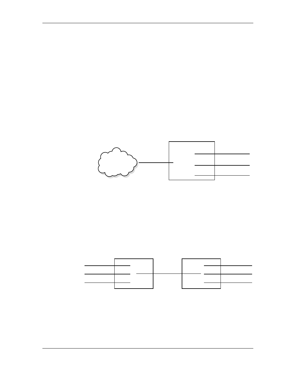
Example 1
PSTN Connection Dial Plan Configuration
In this example, access to the PSTN is provided by a single PRI line. There-
fore, this line is configured as a Network termination. The remaining cir-
cuits, which feed various types of switched equipment, are configured as
User termination because ATLAS 550 is emulating the network on those
connections (see Figure 11-3).
Figure 11-3. PSTN Connection
Example 2
Point-to-Point Connection Dial Plan Configuration
In this example, ATLAS 550 A operates as the network while ATLAS 550 B
terminates the network. That is, ATLAS 550 A emulates the network and its
PRI interface acts as the User termination. The PRI interface of ATLAS 550 B
acts as the Network termination (see Figure 11-4).
Figure 11-4. Point-to-Point Connection
PRI Network
USER
USER
USER
DSX T1 to PBX
Network
ATLAS 550
BRI
BRI
USER
BRI
USER
BRI
USER DSX T1 to PBX
BRI
USER
BRI
USER
T1 from PBX USER
User
Term
PRI
Network
Term
Interface
ATLAS 550 A
ATLAS 550 B