Example 2: ip routing network—external routers – ADTRAN Atlas 550 User Manual
Page 223
Appendix C. Frame Relay Examples
61200305L1-1
ATLAS 550 User Manual
C-3
Step 4
From
D
EDICATED
M
APS
/C
REATE
/E
DIT
M
APS
/C
ONNECTS
, attach the packet
endpoint to the appropriate physical interface (see Figure C-6).
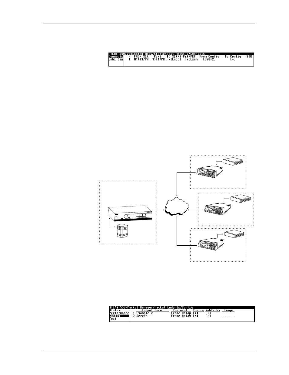
Figure C-6. Menu for Attaching Packet Endpoint to Physical Interface
Example 2:
IP Routing Network—External Routers
Example 2 (see Figure C-7) depicts an IP network with external routers. An
ATLAS 550 is located at the central site. A TSU 100e with an external router
connected to an Nx56/64 module is located at each of two remote sites, and
an FSU with an external router is located at the third remote site. At the cen-
tral site, ATLAS 550 terminates a full T1 frame relay connection from the
XYZ service provider and switches the PVCs to the external router. To re-
create this example, follow the process discussed below.
Figure C-7. IP Network With External Routers
Step 1
From
P
ACKET
M
ANAGER
/P
ACKET ENDPOINTS
/C
ONFIG
, create the packet end-
points (see Figure C-8).
Figure C-8. Menu for Creating the Packet Endpoints
XYZ Public
Frame Relay
F-T1
F-T1
DDS
TSU 100e
ATLAS 550
FSU
TSU 100e
Chicago
Boston
New York
Atlanta
T1
Router
Router
Router
Server
POWER
REMOTE
ERROR
TEST
OK
TEST
ONLINE
STATUS
ERROR
TEST
OK
CRAFT
ACO
ALARM
ALARM
1
2
NETWORK
1
2
3
4
MODULES
SYSTEM
ETHERNET
ATLAS 550