ADTRAN Atlas 550 User Manual
Page 228
Appendix C. Frame Relay Examples
C-8
ATLAS 550 User Manual
61200305L1-1
Step 4
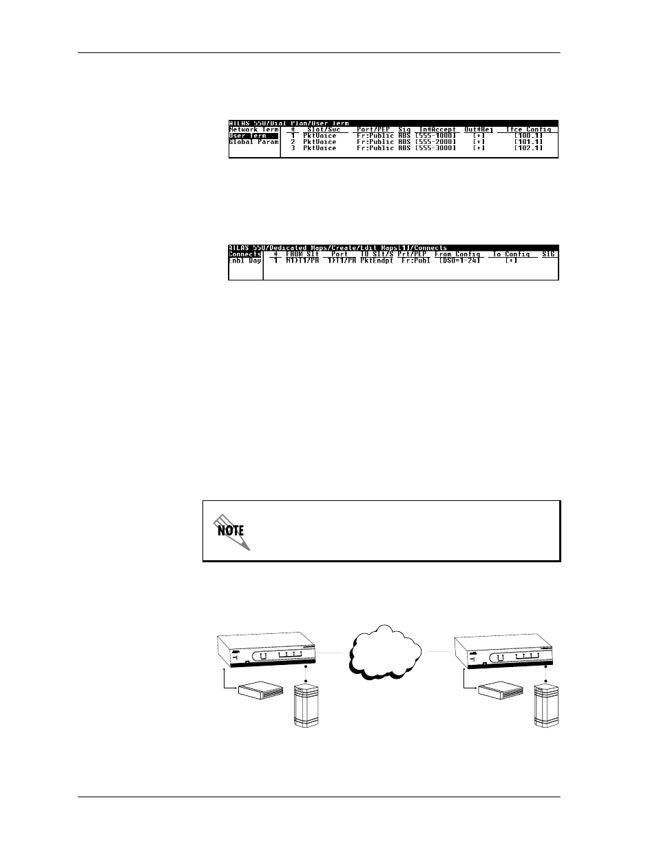
Configure the dial plan for packet voice. Refer to Chapter 11, Dial Plan for
details on configuration (see Figure C-22).
Figure C-22. Menu for Configuring Dial Plan
Step 5
Connect the packet endpoint to the physical interface (see Figure C-23).
Figure C-23. Menu for Connecting Packet Endpoints
Example 5:
Private Frame Relay Network—Packet Voice
Example 5 (see Figure C-24) shows a private frame relay network using
compressed voice. An ATLAS 550 is located at two sites (Atlanta and
Boston) and a PBX is connected to each ATLAS 550 using a clear-channel T1
connection. Each PBX uses DS0s 1—23 for voice and DS0 24 for signaling; all
calls are to be completely managed by the PBXs. In this network, the ATLAS
550 does not terminate the signaling information, but forwards the signaling
between endpoints using a transparent bit oriented protocol (TBOP) frame
relay connection (requires the Voice Compression Module). To re-create this
example, follow the process discussed below.
Figure C-24. Private Frame Relay Network Using Compressed Voice
Packet voice transmission requires the
V
OICE
C
OMPRESSION
M
ODULE
.
Router
PBX
Atlanta
Router
PBX
Boston
Private
Frame Relay
Network
POWER
REMOTE
ERROR
TEST
OK
TEST
ONLINE
STATUS
ERROR
TEST
OK
CRAFT
ACO
ALARM
ALARM
1
2
NETWORK
1
2
3
4
MODULES
SYSTEM
ETHERNET
ATLAS 550
ATLAS 550
ATLAS 550
POWER
REMOTE
ERROR
TEST
OK
TEST
ONLINE
STATUS
ERROR
TEST
OK
CRAFT
ACO
ALARM
ALARM
1
2
NETWORK
1
2
3
4
MODULES
SYSTEM
ETHERNET
ATLAS 550