Frame relay examples, Appendix c, Frame relay network – ADTRAN Atlas 550 User Manual
Page 221
61200305L1-1
ATLAS 550 User Manual
C-1
Appendix C
Frame Relay Examples
This chapter provides step-by-step examples to help you configure your AT-
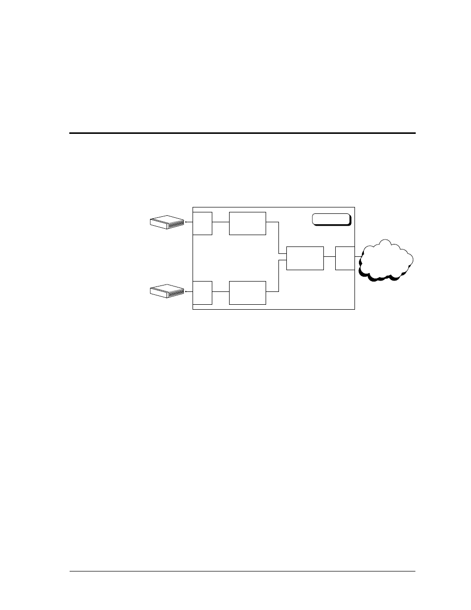
LAS 550 for frame relay. Figure C-1 illustrates an ATLAS 550 configured to
support packet data.
Figure C-1. ATLAS to Support Packet Data Configuration
The general procedure for configuring the ATLAS 550 depicted in Figure C-1
is as follows:
1.
From
P
ACKET
M
ANAGER
/
P
ACKET
E
NDPNTS
/
C
ONFIG
, create three packet
endpoints.
2.
From
P
ACKET
M
ANAGER
/
P
ACKET
C
NCTS
, make the IP and SNA protocol
connections.
From
D
EDICATED
M
AP
, connect the packet endpoints to the physical ports.
EXAMPLE 1:
IP ROUTING NETWORK—ATLAS 550 AS THE
CENTRAL-SITE ROUTER
Example 1 (see Figure C-2 on page C-2) depicts a typical IP routing network
using an ATLAS 550 as the central-site router. A TSU 100e with a router
module is located at each of the two remote sites, and an FSU with an
external router is located at a third site. The central-site ATLAS 550
terminates a full T1 frame relay connection from the XYZ service provider,
and the internal router terminates the IP traffic. To re-create this example,
follow the process that follows.
Frame Relay
Network
IP
SNA
Router
SNA Router
Nx
Port
Pkt
Endpoint 2
Nx
Port
Pkt
Endpoint 3
Pkt
Endpoint 1
T1
Port
ATLAS 550