Control/chain in port – ADTRAN Atlas 550 User Manual
Page 40
Chapter 2. Installation
2-4
ATLAS 550 User Manual
61200305L1-1
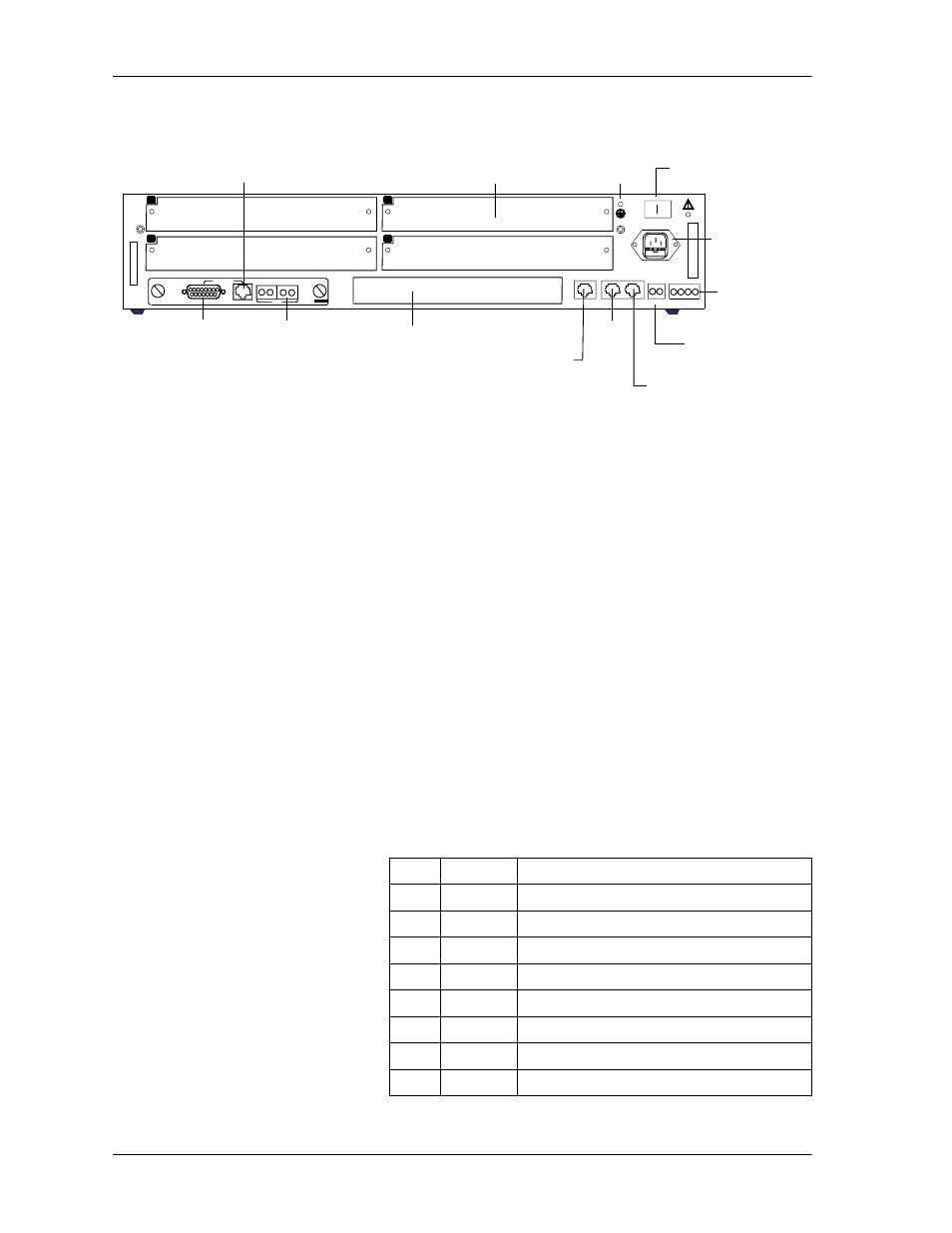
Figure 2-1. ATLAS 550 Rear Panel
Control/Chain In Port
The Control/Chain In port (EIA-232) connects to a computer or modem or
to another ATLAS 550 Base Unit. The control port input provides the follow-
ing functions:
•
Accepts EIA-232 input from a PC or a modem for controlling the ATLAS
550.
•
Operates at 2400, 9600, 19200, or 38400 bps.
•
Acts as input for either PC control or a chained connection.
•
Acts as an interface for flash memory software downloads using
XMODEM.
The Control/Chain In connection follows, and Table 2-1 shows the pinout.
NETWORK 1
NETWORK 2
1
2
3
4
ETHERNET
CONTROL
IN
OUT
RELAY
ALARM
O
I
FUSE RATING: 2A/250V SLO-BLO
90-240VAC, 2A, 50/60Hz
NC NO COM GND
ALL
E
MPTY
SLOTS
MUST
B
E
COVERED
WITH
BLANK
P
ANELS
CAUTION:
FOR
CONTINUED
PROTECTION
AGAINST
RISK
OF
FIRE,
REPLACE
ONL
Y
WITH
SAME
T
YPE
AND
R
A
T
ING
O
F
F
USE.
MON
NETWORK
IN
OUT
IN
OUT
NETWORK
MON
T1 NETWORK MODULE
TEST
500 Series
Blank Panel
Covering an
Unused Network Slot
Blank Panel
Covering an
Unused Option Slot
Network 1
DB-15
Connection
Port
Network 1
RJ-48C
Connection
Port
Bantam
Test Jacks
Power
Switch
Supplemental
Earth
Ground Lug
AC Power
Receptacle
Alarm Relay
Connection
External Alarm Relay
Monitor Connection
Control/
Chain
In
Control/
Chain
Out
RJ-48C
Ethernet
10/100BaseT
Connection
Port
O I
Connector type
RJ-48C
Part number
AMP# 555164-2
Table 2-1. Control/Chain In Pinout
PIN
NAME
DESCRIPTION
1
GND
Ground - connected to unit chassis
2
RTS
Request to send - flow control
3
RXDATA
Data received by the ATLAS 550
4
DTR
Data terminal ready
5
TXDATA
Data transmitted by the ATLAS 550
6
CD
Carrier detect
7
UNUSED —
8
CTS
Clear to send - flow control