ADTRAN Atlas 550 User Manual
Page 140
Chapter 10. Dedicated Maps
10-10
ATLAS 550 User Manual
61200305L1-1
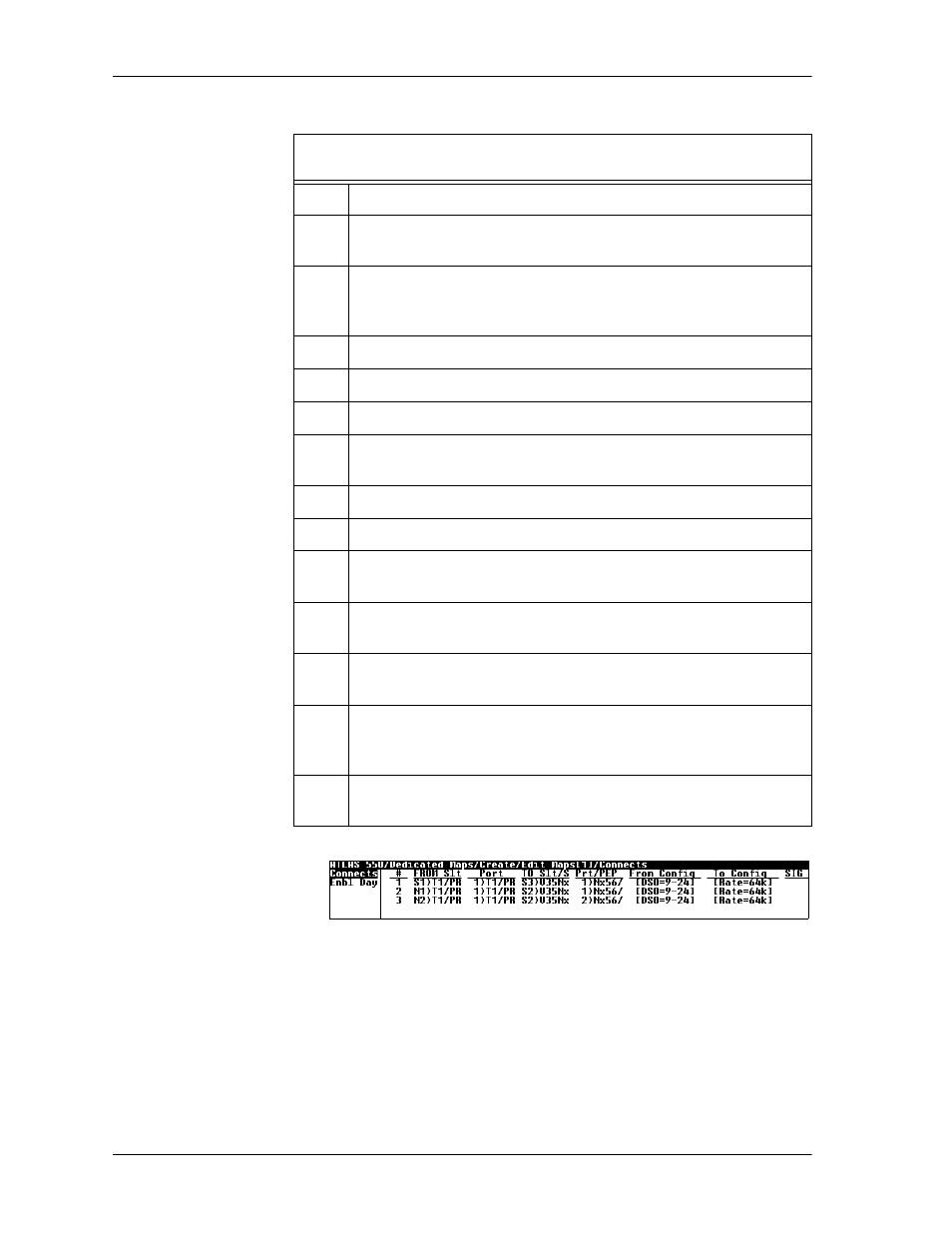
Figure 10-7. Data Connections
Instructions for Defining the Data Connections
(DS0s 9-24)
Step
Action
1
Name your map by navigating to D
EDICATED
M
APS
/ C
REATE
/E
DIT
M
APS
and entering a name.
2
Navigate to the C
REATE
/E
DIT
M
APS
field, C
ONNECTS
.
This field defines the connections necessary to route the required
bandwidth.
3
For T1-A Data, select and define FROM S
LOT
as
N1) T1/PRI-1
.
4
Select and define the “from” P
ORT
as 1)T1/PRI.
5
Select and define TO S
LT
/S as S2) V35N
X
; S2) represents Slot 2.
6
Select and define P
RT
/PEP as 1) N
X
56/64; 1) represents Port 1 of
Slot 2.
7
Select and define F
ROM
C
ONFIG
DS0s as 9-24.
8
Set the V.35 to operate at 64k per DS0 in T
O
C
ONFIG
, [R
ATE
=64
K
].
9
Repeat these steps for the remaining data connections (i.e., T1-B
and T1-C) as follows:
9a
Copy the current connection by positioning the cursor on the index
# and pressing
C
.
9b
Insert new connection lines by positioning the cursor over the
index # of the current connection and pressing I on the keyboard.
9c
Paste this information onto a new connection line by positioning
the cursor over the index number of the new connection, and
pressing
P
.
10
Modify these connection lines to complete the connections for data
(see Figure 10-7).