ADTRAN Atlas 550 User Manual
Page 224
Appendix C. Frame Relay Examples
C-4
ATLAS 550 User Manual
61200305L1-1
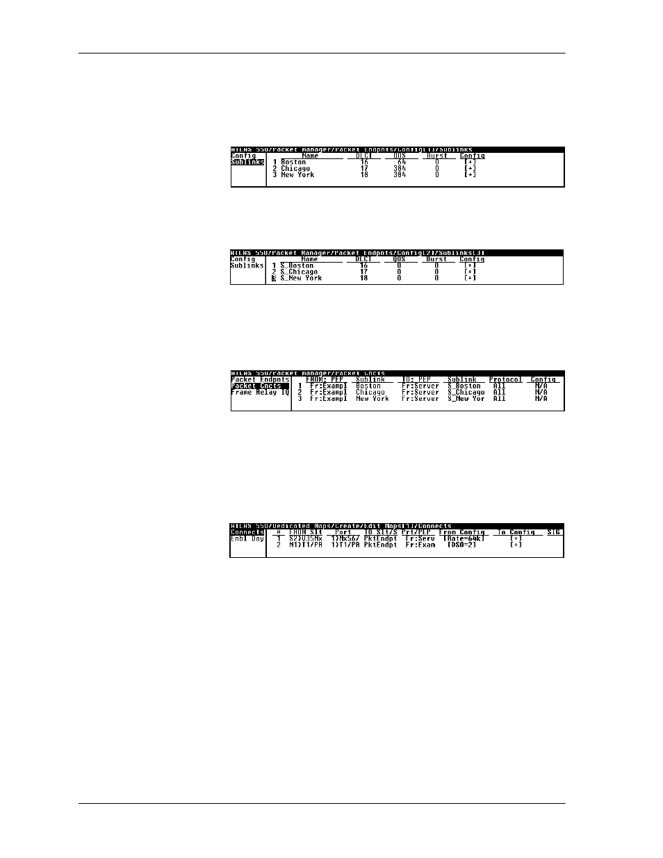
Step 2
From
P
ACKET
M
ANAGER
/P
ACKET
E
NDPOINTS
/C
ONFIG
/S
UBLINKS
, configure
the sublinks for both packet endpoints. For simplicity, use the same DLCI
number going to the server as going to the frame relay network (see Figure
C-9 and Figure C-10).
Figure C-9. Menu for Configuring Packet Endpoints (1) Sublinks
Figure C-10. Menu for Configuring Packet Endpoints (2) Sublinks
Step 3
Make the packet connections (see Figure C-11).
Figure C-11. Menu for Making the Packet Connections
Step 4
Connect the packet endpoints to the physical port. The server connects to an
Nx56/64 module, and the frame relay network connects to a T1 port on the
controller (see Figure C-12).
Figure C-12. Menu for Connecting Packet Endpoints to Physical Port
Example 3:
Private Frame Relay Network—ATLAS 550 Central-
Site Router
Example 3 (see Figure C-13 on page C-5) depicts a private frame relay
network using ATLAS 550 as the central-site router and a frame relay
switch. A TSU 100e with a router module is located at each of three remote
sites. At the central site, ATLAS 550 terminates a full T1 with eight DS0s
from each of the remote sites DACSed onto the single T1. (See, also, the
discussion of DACSing in the ATLAS 550 User Manual.) To re-create this
example, follow the process discussed below.