Operation – KROHNE MFC 300 EN User Manual
Page 90
6
OPERATION
90
MFC 300
www.krohne.com
02/2012 - 4000498602 - MA MFC 300 R03 en
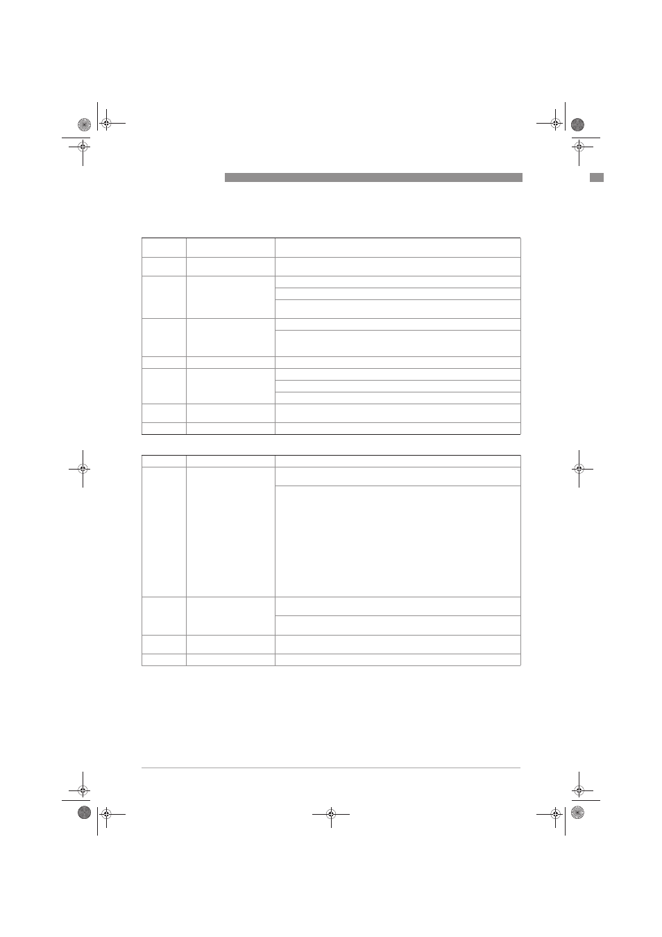
C3. Limit Switch X
C3.
Limit Switch X
X stands for one of the connection terminals A, B, C or D
stands for Fct. no. C3.2 (A) / C3.3 (B) / C3.4 (C) / C3.5 (D)
C3. .1
Measurement
Select: Volume Flow / Mass Flow / Diagnosis 1...3 / Flow Velocity /
Temperature / Concentration Flow 1 / Density
C3. .2
Threshold
Switching level, set threshold with hysteresis
xxx.x ±x.xxx (format and unit depend on the measurement, see above)
(1st value = threshold / 2nd value = hysteresis),
condition: 2nd value ≤ 1st value
C3. .3
Polarity
Set polarity, please note Flow Direction in C1.3.2!
Select: both polarities (plus and minus values are displayed) / positive
polarity (display for negative values = 0) / negative polarity (display for
positive values = 0) / absolute value (use for the output)
C3. .4
Time Constant
Range: 000.1…100 s
C3. .5
Invert Signal
Select:
Off (activated output generates a high current, switch closed)
On (activated output generates a low current, switch open)
C3. .6
Information
Serial no. of the I/O board, software version no. and production date of the
circuit board
C3. .7
Simulation
Sequence see B1. limit switch X
C3. Control Input X
C3.
Control Input X
C3. .1
Mode
X stands for connection terminal A or B
stands for Fct. no. C3.2 (A) / C3.3 (B)
Off (control input switched off) /
hold all outputs (hold current values, not display and totalisers) /
output Y (hold current values) /
all outputs to zero (current values = 0%, not display and totalisers) /
output Y to zero (current value = 0%) /
all totalisers (reset all totalisers to "0") /
totaliser "Z" reset (set totaliser 1, (2 or 3) to "0") /
stop all totalisers /
stop totaliser "Z" (stops totaliser 1, (2 or 3) /
zero outp.+stop Tot. (all outputs 0%, stop all totalisers, not the display) /
external range Y (control input for external range of current output Y) - also
make this setting on current output Y (no check if current output Y is
available) /
Error reset (all resettable errors are deleted)
Zero Calibration
C3. .2
Invert Signal
off (control input is activated when a current is applied at the input by voltage
to passive inputs or a low-value resistor to active inputs)
on (control input is activated when no current is applied at the input, low
voltage to passive inputs or a high-value resistor to active inputs)
C3. .3
Information
Serial no. of the I/O board, software version no. and production date of the
circuit board
C3. .4
Simulation
Sequence see B 1. control input X
.book Page 90 Monday, February 6, 2012 11:01 AM