Operation – KROHNE MFC 300 EN User Manual
Page 83
OPERATION
6
83
MFC 300
www.krohne.com
02/2012 - 4000498602 - MA MFC 300 R03 en
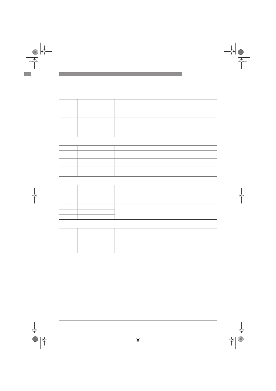
C1.3 Filter
C1.3
Filter
C1.3.1
Flow Direction
Define polarity of flow direction.
Forwards (according to the arrow on the measuring sensor) or backwards
(in the opposite direction to the arrow)
C1.3.2
Press. Supp. Time
Set the pressure suppression time, range: 0.0...20.0 s
C1.3.3
Press. Supp. Cutoff
Cutoff settings for the pressure suppression; range: 0.0...10.0%
C1.3.4
Density Averaging
Set the time constant for the density measurements; range: 1.0...20.0 s
C1.3.5
Low Flow Cutoff
Set the low flow cutoff; range: 00.0...10.0%
C1.4 System Control
C1.4
System Control
C1.4.1
Function
Set the system control.
Select: inactive (off) / flow = 0 (flow to zero)
C1.4.2
Sys. Ctrl. Condition
Set the condition for activating the system control.
Selection: density or temperature
C1.4.3
Sys. Ctrl. Max Limit
Defines the upper limit for the condition selected in C1.4.2
C1.4.4
Sys. Ctrl. Min Limit
Defines the lower limit for the condition selected in C1.4.2
C1.5 Self Test
C1.5
Self Test
C1.5.1
Max. Rec. Temp.
Display of maximum recorded sensor temperature
C1.5.2
Min. Rec. Temp.
Display of minimum recorded sensor temperature
C1.5.3
2 Ph. Threshold
Defines the process-dependent sensitivity for 2 phase signal error message.
C1.5.4
Diagnosis 1
Defines the parameter for the respective diagnostic value.
Select: off (goes to zero) / sensor average (sensor amplitude A+B) / sensor
deviation / drive level / MT frequency / strain MT / strain IC / 2 phase signal
C1.5.5
Diagnosis 2
C1.5.6
Diagnosis 3
C1.6 Information
C1.6
Information
C1.6.2
V No. Sensor
Shows the order number of the measuring sensor.
C1.6.3
SE Serial No.
Displays the serial number of the sensor electronics
C1.6.4
SE Version
Displays the version of the sensor electronics
C1.6.5
SE Interface
Displays the interface version of the sensor electronics
.book Page 83 Monday, February 6, 2012 11:01 AM