Operation, Operation 6.1 display and operating elements – KROHNE MFC 300 EN User Manual
Page 69
OPERATION
6
69
MFC 300
www.krohne.com
02/2012 - 4000498602 - MA MFC 300 R03 en
Operation
6.1 Display and operating elements
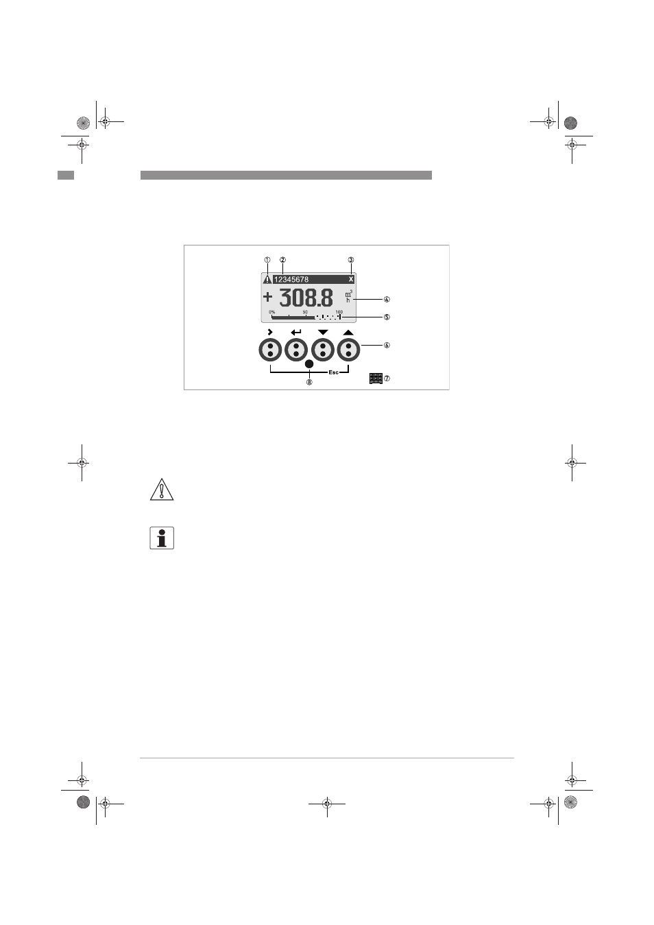
Figure 6-1: Display and operating elements (Example: flow indication with 2 measuring values)
1 Indicates a possible status message in the status list
2 Tag number (is only indicated if this number was entered previously by the operator)
3 Indicates when a key has been pressed
4 1st measured variable in large representation
5 Bargraph indication
6 Keys (see table below for function and representation in text)
7 Interface to the GDC bus (not present in all signal converter versions)
8 Infrared sensor (not present in all signal converter versions)
CAUTION!
The use of a jumper is only permitted for custody transfer devices to lock the access to custody
transfer relevant parameters. For non custody transfer devices (i.e. process instruments) this
jumper must not be used!
INFORMATION!
•
The switching point for the 4 optical keys is located directly in front of the glass. It is
recommended to activate the keys at right angles to the front. Touching them from the side
can cause incorrect operation.
•
After 5 minutes of inactivity, there is an automatic return to measuring mode. Previously
changed data is not saved.
.book Page 69 Monday, February 6, 2012 11:01 AM