Lincoln Electric IM8002 POWER WAVE MANAGER User Manual
Page 110
Appendix B. FANUC Robots
FANUC® Robot Application (Prior to v7.70P/21)
B.4
Power Wave® Manager User Manual
IM8002
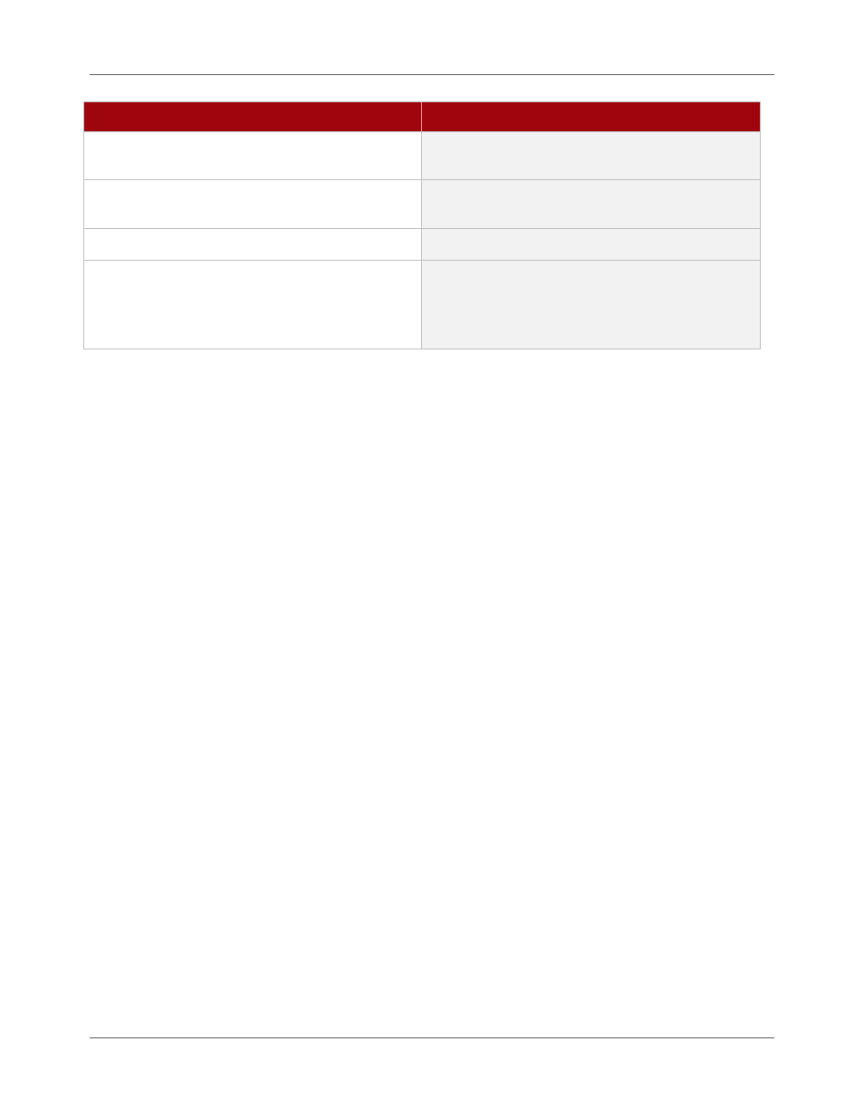
Procedure
Details
4.
Cursor to PM_SEL or PM_VER and press
Enter.
5.
With the cursor now just past the PM_SEL or
PM_VER, press F4-Choice.
6.
Cursor to Constant and press Enter.
The word “Constant” now appears on the line.
7.
Select the Weld Profile number you want to
assign and press Enter.
Instruction is now complete and should appear
similar to the example program above. Now,
whenever this program is run, that Weld Profile
will be monitored.
Alarm/Alert Programs
Whenever a weld goes out of limits, the system posts an alarm to the top of the teach pendant screen. It
may be desirable for additional actions to take place such as a warning light to illuminate. Six additional
programs are installed in the robot for ease of adding additional actions to take place. These programs are
titled ALERT_1 through ALERT_5, and ALERT_10. They are used as follows:
ALERT_1
Weld Profile Runt occurred
ALERT_2
Weld Profile Time Limit occurred
ALERT_3
Weld Profile I (current) Limit occurred
ALERT_4
Weld Profile V (voltage) Limit occurred
ALERT_5
Weld Profile WFS (wire feed speed) occurred
ALERT_10
Invalid Profile has been selected
The program names have already been created but it is the end user’s responsibility to set these programs
up as needed and to install the necessary electrical and mechanical interfaces necessary to allow these
programs to work. Refer to the FANUC® Controller Electrical Connection and Maintenance Manual for
interfacing instructions.
Here is an example program:
ALERT_4
1: DO[1] = ON
2: WAIT UI[6] = ON
3: DO[1] = OFF
END
This program turns on Digital Output [1] if a Voltage Limit occurs. DO[1] may be wired to an indicator light
to alert the operator if a Voltage Limit has occurred. The light will remain on until User Input [6] is received,
which may be triggered by a reset switch located near the indicator light. Then Digital Output [1] turns off,
turning off the indicator light.