Pid function block, 1 general, 2 modes – Yokogawa YVP110 User Manual
Page 82: 3 input processing, 4 setpoint (sp) limiters, Pid function block -1, General -1, Modes -1, Input processing -1, Setpoint (sp) limiters -1
<16. PID Function Block>
16-1
IM 21B04C01-01E
16. PID Function Block
16.1 General
The PID function block receives an input signal,
performs PID control computation, and outputs
the control signal, like a single-loop controller. In
practice, it performs PID computation based on
the deviation between the setpoint set in the actual
mode and the PV, and generates a value of its
output OUT so as to decrease the deviation. The
PID block works with other function blocks such as
the AI and AO blocks connected to it. The major
functions of the PID block include:
• Filtering
• Setpoint limiters - both for the value and rate of
change
• Scaling of process variable (PV), setpoint (SP),
and output (OUT)
• PID control computation
• Control action bypass
• Feed-forward
• External-output tracking
• Measured-value tracking
• Output limiters
• Mode shedding upon computer failure
• Alarm generation
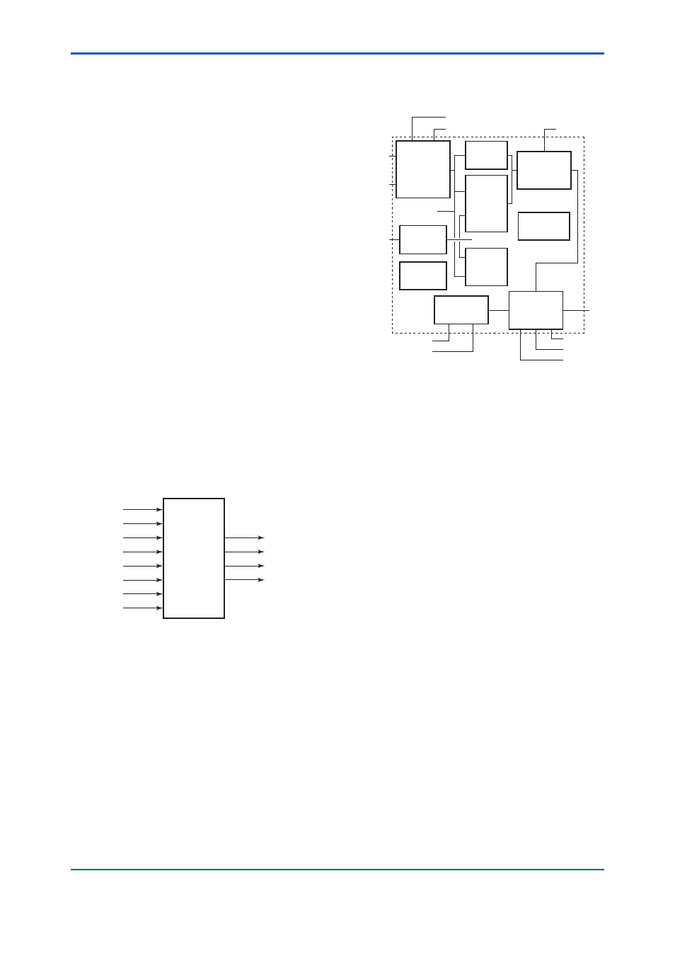
F1601.ai
PID
FF_VAL
ROUT_OUT
TRK_VAL
RCAS_OUT
TRK_IN_D
OUT
ROUT_IN
RCAS_IN
CAS_IN
BKCAL_IN
IN
BKCAL_OUT
Figure 16.1 Inputs/Outputs of PID Function Block
F1602.ai
OUT
ROUT_OUT
FF_VAL
RCAS_OUT
BKCAL_OUT
BKCAL_IN
TRK_IN_D
TRK_VAL
ROUT_IN
Setpoint
SP_RATE_DN
SP_RATE_UP
SP_HI_LIM
SP_LO_LIM
Bypass
BYPASS
Feed Forward
FF_SCALE
FF_GAIN
Status
BKCAL_HYS
Output Track
TRK_SCALE
Filter
PV_FTIME
MODE
SHED_OPT
Output
OUT_HI_LIM
OUT_LO_LIM
Control
GAIN
RESET
BAL_TIME
RATE
Alarm
HI/LO
DEL
CAS_IN
RCAS_IN
SP
IN
PV
Figure 16.2 Function Diagram of PID Function
Block
16.2 Modes
The target mode for the PID function block can be
set from five block modes: ROut, RCas, Cas, Auto,
Man, and O/S. Regardless of the target mode,
the PID block automatically enters the IMan or
LO mode when a specified condition is met (such
as when another function block enters a specific
status), depending on the parameter settings.
16.3 Input Processing
The input signal to IN is filtered through a lag filter
whose time constant is set in PV_FTIME, and then
set as the process variable (PV).
16.4 Setpoint (SP) Limiters
The path for computing the SP differs depending
on the mode. In Cas mode, CAS_IN is used for
SP. In RCas mode, RCAS_IN is used for SP. If the
value of CAS_IN or RCAS_IN, whichever is used,
is greater than SP_HI_LIM (high limit) or less than
SP_LO_LIM (low limit), the internal SP is set to the
respective limits. When the target mode is Auto or
Man, and when SP-PV tracking is not specified at
the same time, the rate of change in the setpoint
is also limited (by the values of SP_RATE_UP and
SP_RATE_DN).