Os function block, 1 general, 2 modes – Yokogawa YVP110 User Manual
Page 80: 3 output processing, Os function block -1, General -1, Modes -1, Output processing -1
<15. OS Function Block>
15-1
IM 21B04C01-01E
15. OS Function Block
15.1 General
The OS (output splitter) function block is used
to split a single control signal into two parts for
coordinating the actions of two or more valves, such
as for split-range control or sequencing control of
a large and a small valves. The OS block receives
a control signal and converts it into two signals in
accordance with the predefined relationships. The
major functions of the OS block include:
• Conversion of the setpoint (SP) value into
two output values (OUT_1 and OUT_2)
in accordance with the user-specified
characteristics (set in IN_ARRAY and OUT_
ARRAY)
• Generation of the output value to be fed back to
the upstream block (BKCAL_OUT)
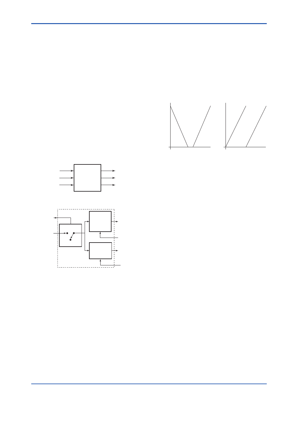
F1501.ai
OS
CAS_IN
BKCAL_IN_1
BKCAL_IN_2
BKCAL_OUT
OUT_1
OUT_2
Figure 15.1 Inputs/Outputs of OS Function Block
F1502.ai
Output
X21, X22
Y21, Y22
BKCAL_IN_1
Cas
Auto
SP
BKCAL_OUT
OUT_1
CAS_IN
OUT_2
BKCAL_IN_2
Output
X11, X12
Y11, Y12
LOCKVAL
Figure 15.2 Function Diagram of OS Function
Block
15.2 Modes
The target mode for the OS function block can
be set from three block modes: Cas, Auto, and
O/S. Regardless of the target mode, the OS
block automatically enters the IMan mode when a
specified condition is met.
15.3 Output Processing
The values of OUT_1 and OUT_2 with respect to
the value of SP, which is the value of the input from
the upstream block (CAS_IN) in the Cas mode
or the local setpoint value in the Auto mode, are
determined as shown in the following graphs.
F1503.ai
Split-range Control
Valve Sequencing Control
100%
50%
0%
P1
(X11, Y11)
OUT_1 OUT_2
P3
(X21, Y21)
P2
(X12, Y12)
P4
(X22, Y22)
0%
50%
100%
SP
100%
50%
0%
P1
(X11, Y11)
OUT_1
OUT_2
P4
(X22, Y22)
P2
(X12, Y12)
P3
(X21, Y21)
0%
50%
100%
SP
OUT
OUT
Figure 15.3 Examples of Valve Operation
Characteristics
These characteristics are determined by the array
element values in parameters IN_ARRAY and
OUT_ARRAY.
IN_ARRAY: [X11, X12, X21, X22]
OUT_ARRAY: [Y11, Y12, Y21, Y22]
Coordinates P1 (X11, Y11) and P2 (X12, Y12)
define the start and stop points of the characteristics
for OUT_1, and P3 (X21, Y21) and P4 (X22, Y22)
define those for OUT_2. These two operation
characteristics may overlap each other, or start from
the same point and have different slopes; however,
all the following conditions must be met at all times.
Settings of IN_ARRAY that do not meet one or
more of these conditions cause a BLOCK_ERR,
disabling the block from exiting the O/S mode.
X21 ≥ X11
X12 > X11
X22 > X21
In areas outside the endpoints (i.e., start and stop
points) of each operation characteristic, the output
is retained at the Y value at the nearer end point.
For OUT_1, however, depending on the setting of
LOCKVAL, it is possible to:
Set the value of OUT_1 to Y11 in the areas
outside the endpoints if SP is greater than X12
and if LOCKVAL is false.