A-23 – Yokogawa YVP110 User Manual
Page 134
A-23
IM 21B04C01-01E
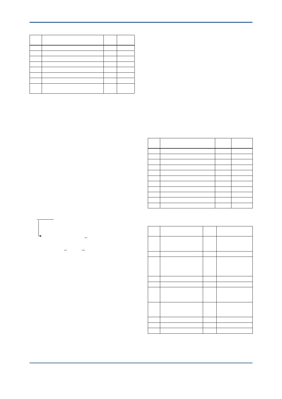
(2) DlmeLinkMasterInfoRecord
Sub-
index
Element
Size
[bytes]
Descrip-
tion
1
MaxSchedulingOverhead
1
V(MSO)
2
DefMinTokenDelegTime
2
V(DMDT)
3
DefTokenHoldTime
2
V(DTHT)
4
TargetTokenRotTime
2
V(TTRT)
5
LinkMaintTokHoldTime
2
V(LTHT)
6
TimeDistributionPeriod
4
V(TDP)
7
MaximumInactivityToClaimLasDelay
2
V(MICD)
8
LasDatabaseStatusSpduDistribution
Period
2
V(LDDP)
(3) PrimaryLinkMasterFlagVariable
Explicitly declares the LAS. Writing “true” (0xFF)
to this parameter in a device causes that device to
attempt to become the LAS. However, a request
of writing “true” to this parameter in a device is
rejected if the value of the same parameter in any
other device that has a smaller node address within
the same segment is true.
(4) LiveListStatusArrayVariable
A 32-byte variable, in which each bit represents the
status of whether a device on the same segment
is live or not. The leading bit corresponds to the
device address 0x00, and final bit to 0xFF. The
value of LiveListStatusArrayVariable in the case
where devices having the addresses 0x10 and
0x15 in the fieldbus segment is shown below.
0x00 00 84 00 00 00 00 00 00 00 00 00 00 00
00 00 00 00 00 00 00 00 00 00
00 00 00 00 00 00 00 00
Bit correspondences: 0 0 0 0 0 0 0 0 0 0 0
0Ч00
0 0 0 0 0 1 0 0 0 0 1 0 0...
0Ч10
0Ч15
(5) MaxTokenHoldTimeArray
An 8(64 byte array variable, in which each set of
2 bytes represents the delegation time (set as an
octet time) assigned to a device. The delegation
time denotes a time period that is given to a device
by means of a PT message sent from the LAS
within each token circulation cycle.
The leading 2 bytes correspond to the device
address 0x00, and the final 2 bytes to the device
address 0xFF. Specify the subindex to access this
parameter.
(6) BootOperatFunctionalClass
Writing 1 to this parameter in a device and
restarting the device causes the device to start as
a basic device. On the contrary, writing 2 to this
parameter and restarting the device causes the
device to start as an LM.
(7) CurrentLinkSettingRecord and
ConfiguredLinkSettingsRecord
CurrentLinkSettingRecord indicates the
bus parameter settings currently used.
ConfiguredLinkSettingsRecord indicates the
bus parameter settings to be used when the
device becomes the LAS. Thus, when a device
is the LAS, its CurrentLinkSettingRecord and
ConfiguredLinkSettingsRecord have the same
values.
Sub-
index
Element
Size
[bytes]
Descrip-
tion
1
SlotTime
2
V(ST)
2
PerDlpduPhlOverhead
1
V(PhLO)
3
MaxResponseDelay
1
V(MRD)
4
FirstUnpolledNodeId
1
V(FUN)
5
ThisLink
2
V(TL)
6
MinInterPduDelay
1
V(MID)
7
NumConsecUnpolledNodeId
1
V(NUN)
8
PreambleExtension
1
V(PhPE)
9
PostTransGapExtension
1
V(PhGE)
10 MaxInterChanSignalSkew
1
V(PhIS)
11 TimeSyncClass
1
V(TSC)
(8) DlmeBasicInfo
Sub-
index
Element
Size
[bytes]
Description
1
SlotTime
2
Indicates the
capability value for
V(ST) of the device.
2
PerDlpduPhlOverhead
1
V(PhLO)
3
MaxResponseDelay
1
Indicates the
capability value
for V(MRD) of the
device.
4
ThisNode
1
V(TN), node address
5
ThisLink
2
V(TL), link-id
6
MinInterPduDelay
1
Indicates the
capability value for
V(MID) of the device.
7
TimeSyncClass
1
Indicates the
capability value for
V(TSC) of the device.
8
PreambleExtension
1
V(PhPE)
9
PostTransGapExtension
1
V(PhGE)
10 MaxInterChanSignalSkew
1
V(PhIS)