3 signature measurement functions, 1 signature measurement procedure, Signature measurement functions -2 19.3.1 – Yokogawa YVP110 User Manual
Page 106: Signature measurement procedure -2
<19. Diagnostics>
19-2
IM 21B04C01-01E
Each integrated value is associated with a
parameter specifying a threshold. Setting the
desired value for a threshold will raise a block alarm
when that value is reached. The total travel is
useful for various purposes such as for anticipating
possible degradation of the valve and determining
appropriate timing for maintenance. To reset
these integrated values, write 0 to the respective
parameters. Use caution as the previous value
cannot be restored after being reset.
19.3 Signature Measurement
Functions
Acquisition of detailed data is essential to ensure
that changes in valve’s characteristics are captured
and on-target maintenance is performed. The
signature functions measure the input-to-position
characteristics of the valve, and the input-to-
position characteristics and step response of the
positioner while off-line. As for a valve’s input-to-
position characteristics, a function of performing in-
detail measurement is provided to enable miniscule
changes to be captured without fail.
Nevertheless, since a vast amount of measured
data cannot be stored in the limited memory of the
positioner and most of the data would be lost in the
event of a power failure, measured data should
be uploaded from a host as necessary. Further,
the data thus uploaded needs to be processed
for analyses. These requirements make it difficult
to use a general-purpose tool or application for
these tasks. ValveNavi (R2.20 or later) YVP
management software, a YVP-specific tool is
designed to perform these tasks with ease and
offers dedicated functions. ValveNavi facilitates
executions signature measurement, uploads of
measured data, display of measured data in a
graph, and comparisons of measured data with
previously measured data.
This User’s Manual outlines the contents of each
type of signature and explains the signature-
pertaining parameters in the transducer block. For
instructions on performing signature measurement,
see the User’s Manual for ValveNavi (IM
21B04C50-01E, second edition or later), which
explains its functions and operation procedures.
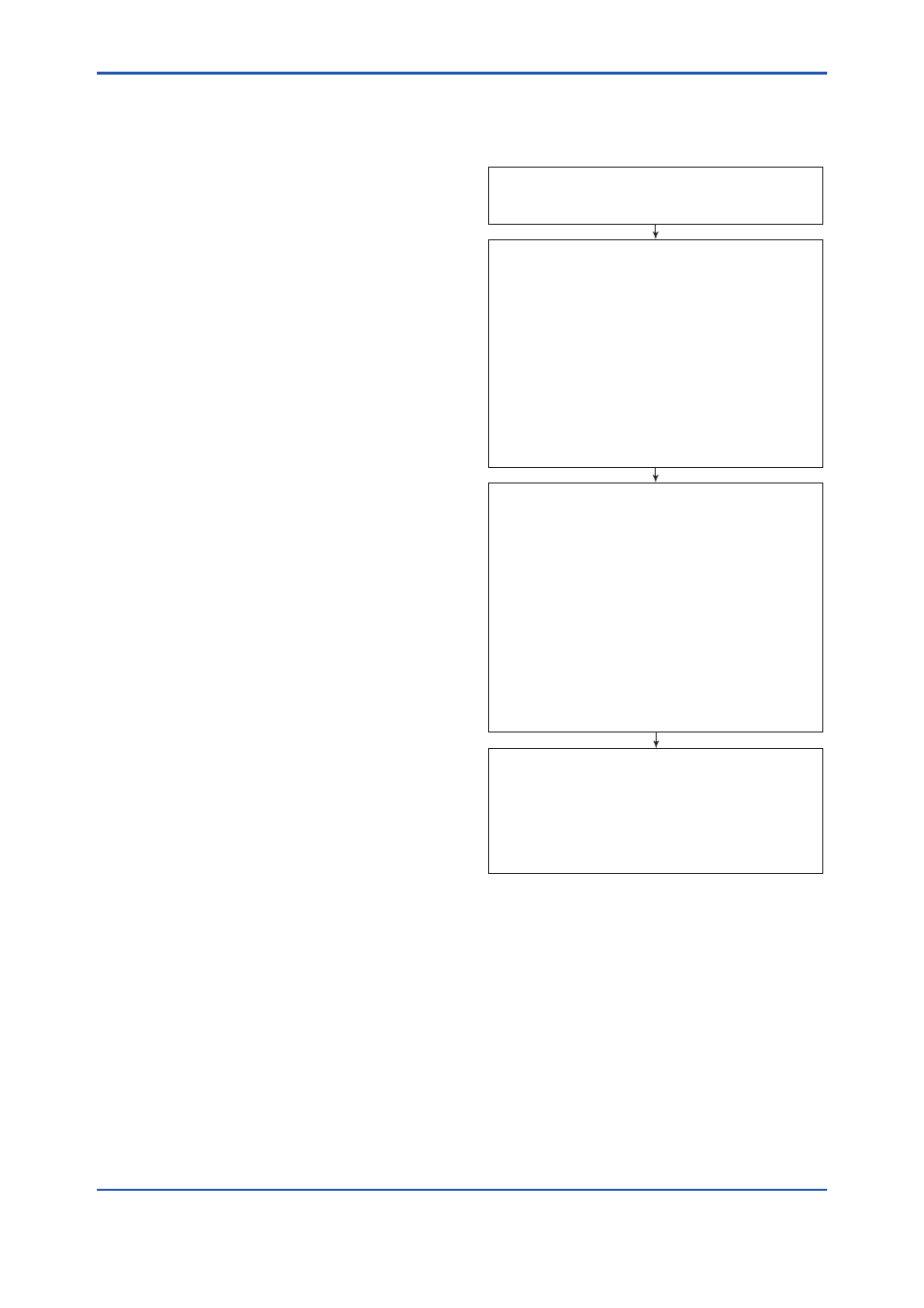
19.3.1 Signature Measurement Procedure
The fundamental procedure for measuring
signatures is as follows.
F1901.ai
After the measurement has finished, set
SIGN_UPLOAD_DATABASE to select the data you
want to upload, and upload the values of
SIGN_DATA_X and SIGN_DATA_Y.
SIGN_UPLOAD_DATABASE
1 Current: Standard Actuator Signature
2 Current: Extended/High Resolution Actuator
Signature
3 Current: Step Response Test
4 Current: Positioner Signature
5 Factory: Standard Actuator Signature
(result stored in non-volatile memory )
6 Record: Standard Actuator Signature
(result stored in non-volatile memory)
Set SIGN_MEAS_EXEC to select the signature(s)
to be measured and carry out the measurement. At
this time, the value of MODE_BLK target in both the
transducer and AO blocks needs to be O/S.
SIGN_MEAS_EXEC
1 Off
2 Measure All (executing 3, 4, 6, 7)
3 Measure Standard Actuator Signature
4 Measure Extended Actuator Signature
5 Measure High Resolution Actuator Signature
6 Measure Step Response Test
7 Measure Positioner Signature
255 Cancel Execution
Set the measurement conditions for the signature(s)
you want to measure in reference with Section
19.3.2.
If the number of the measured data is 20 or more,
specify in SIGN_UPLOAD_POINTER the leading
position of the data to be uploaded. For example,
setting “21” in SIGN_UPLOAD_POINTER will
upload the twenty-first through fortieth data. Refer
to the value of SIGN_MEAS_COUNTER, which
indicates the number of data actually measured.