Transducer block, 1 general, 2 forward path – Yokogawa YVP110 User Manual
Page 70: 1 input from ao block, Transducer block -1, General -1, Forward path -1 12.2.1, Input from ao block -1
<12. Transducer Block>
12-1
IM 21B04C01-01E
12. Transducer Block
12.1 General
The transducer block works as an interface
between the hardware I/O (actuator, sensor) and
internal function blocks. Most functions of the
YVP110 as a valve positioner are packed in the
transducer block. Major functions of the transducer
blocks include:
• Transmission and reception of setpoint and
readback signals for valve position
• Setpoint high/low limiters
• Auto tuning
• Valve tight-shut and full-open actions
• Valve position-to-flow rate characteristics
conversion
• Travel calibration
• Diagnostics of valve and positioner
• Valve position limit switches
• Pressure and temperature measurement
(pressure measurement requires the optional
sensor)
• Fail safe
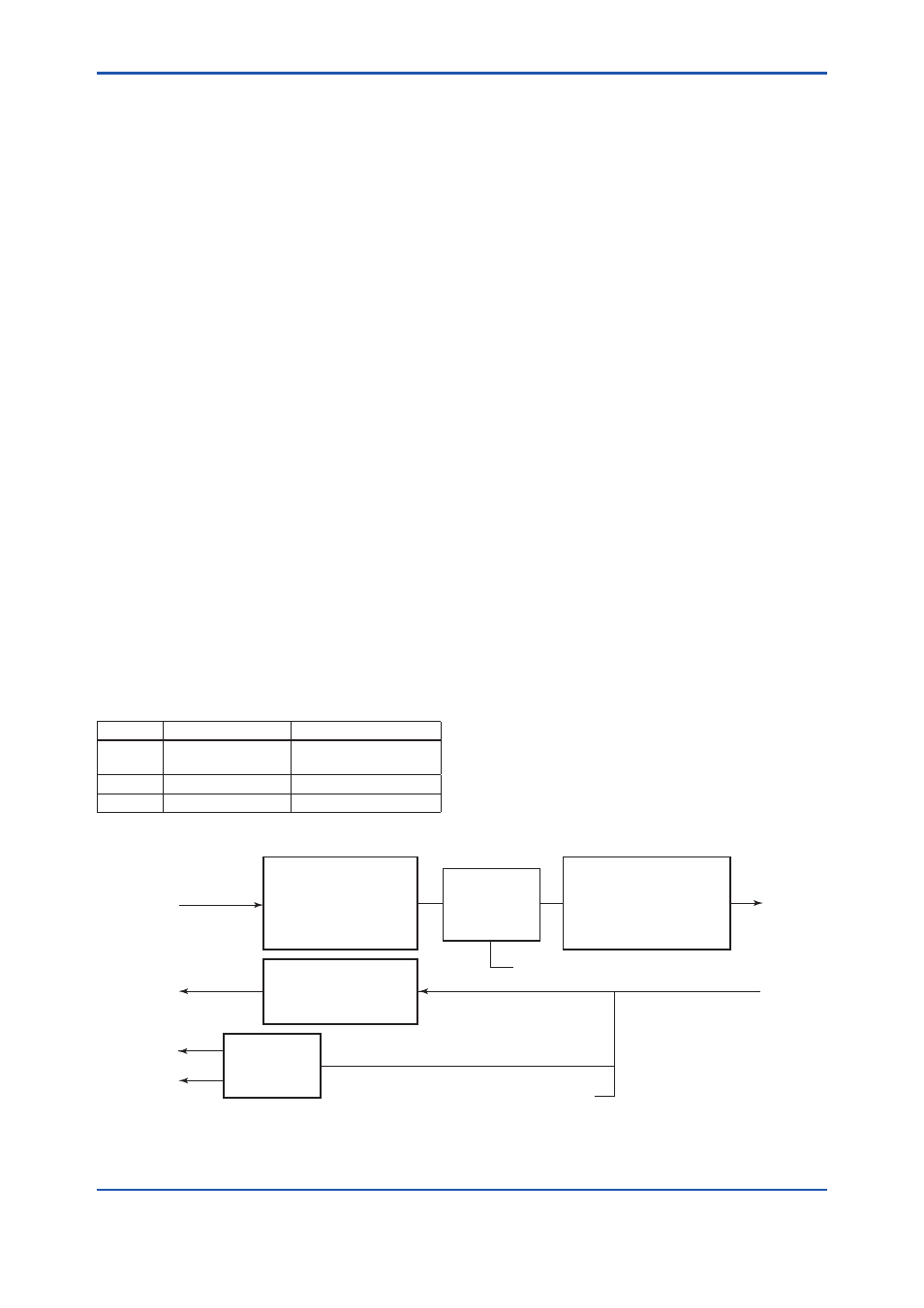
The transducer block in a YVP110 is connected
to an AO function block and two DI blocks via its
channels as shown below.
Table 12.1
Correspondence between Channels
and I/O Signals
Channel
Signal
Description
1
Analog input/output Setpoint and readback
signals
2
Discrete output
High limit switch status
3
Discrete output
Low limit switch status
12.2 Forward Path
The following describes the signal input from the
AO block to the transducer block and then passed
to the device hardware side.
12.2.1 Input from AO Block
The OUT value of the AO block is input to the
transducer block. This input action is halted when:
• The channel number of the AO block is not set
as 1; or
• The AO block is in O/S mode.
Based on the input value from the AO block,
transducer block:
• Performs the flow rate-to-valve position
conversion;
• Limits the setpoint within a specified range; and
• Performs tight-shut or full-open action as
necessary.
The input from the AO block is always a percentage
value where the transducer block always
regards 0% to be the shut-off position. Make
the correct settings at initial setup according to
the specifications of the valve (in reference with
Chapter 5, “Setup”).
F1201.ai
CHANNEL1
FINAL_VALUE
Final Value
POSITION_CHAR_TYPE
POSITION_CHAR
CHANNEL1
FINAL_POSITION_VALUE
AO Readback
POSITION_CHAR_TYPE
POSITION_CHAR
CHANNEL3
CHANNEL2
Limit Switch
LIMSW_HI_LIM
LIMSW_LO_LIM
Limiter
FINAL_VALUE
_RANGE
Tight Shutoff / Full Open
FINAL_VALUE_CUTOFF_HI
FINAL_VALUE_CUTOFF_LO
Figure 12.1 Function Diagram of Transducer Block