3 definition of combining function blocks, Definition of combining function blocks -2 – Yokogawa YVP110 User Manual
Page 52
<9. Configuration>
9-2
IM 21B04C01-01E
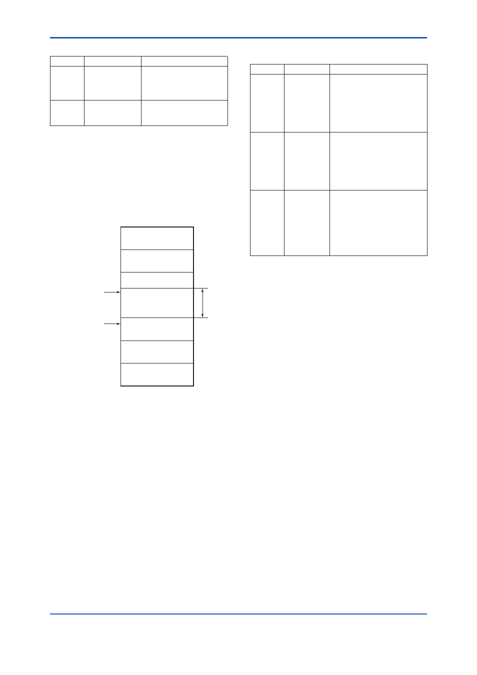
Table 9.1
Parameters for Setting Address Range
Symbol
Parameters
Description
V (FUN) First-Unpolled-
Node
Indicates the address
next to the address range
used for the host or other
LM device.
V (NUN) Number-of-
consecutive-
Unpolled-Node
Unused address range.
The devices within the address range written
as “Unused” in Figure 9.1 cannot be used on a
Fieldbus. For other address ranges, the range is
periodically checked to identify when a new device
is mounted. Care must be taken not to allow the
address range to become wider, which can lead to
exhaustive consumption of Fieldbus communication
performance.
Bridge device
Not used
0x00
0x0F
0x14
0x13
0x10
0xF7
0xF8
0xFB
0xFC
0xFF
V(FUN)
V(FUN)1V(NUN)
LM device
Unused
V(NUN)
BASIC device
Default address
Portable device address
F0901.ai
Figure 9.1
Available Range of Node Addresses
To ensure stable operation of Fieldbus, determine
the operation parameters and set them to the LM
devices. While the parameters in Table 9.2 are to
be set, the worst-case value of all the devices to
be connected to the same Fieldbus must be used.
Refer to the specification of each device for details.
Table 9.2 lists YVP110 specification values.
Table 9.2
Operation Parameter Values of the
YVP110 to be Set to LM Devices
Symbol Parameters
Description and Settings
V (ST)
Slot-Time
Indicates the time necessary
for immediate reply of the
device. Unit of time is in
octets (256 μs).
Set maximum specification
for all devices. For YVP, set a
value of 4 or greater.
V (MID)
Minimum-
Inter-PDU-
Delay
Minimum value of
communication data
intervals. Unit of time is in
octets (256 μs). Set the
maximum specification for all
devices. For YVP, set a value
of 4 or greater.
V (MRD) Maximum-
Reply-Delay
The worst case time elapsed
until a reply is recorded. The
unit is Slottime; set the value
so that V (MRD) 3V (ST) is
the maximum value of the
specification for all devices.
For YVP, the setting must be
a value of 12 or greater.
9.3 Definition of Combining
Function Blocks
The input/output parameters for function blocks
are combined. Practically, setting is written to the
YVP110 link object with reference to “Block setting”
in Section 9.6 for details.
For the YVP110, in order to minimize the delay in
data transfer between Transducer block and AO
function block, transducer block are designed to
be executed in conjunction with the execution of
AO function block. Therefore, in order to activate
Transducer block, it is necessary that AO function
block is always defined in the schedule.
The combined blocks need to be executed
synchronously with other blocks on the
communications schedule. In this case, change the
YVP110 schedule according to the following table.
Enclosed values in the table are factory-settings.
YVP110 schedule is set as shown in the following.
Change it as necessary.