Appendix 5. position adjustment of feedback lever, A-37, Warning – Yokogawa YVP110 User Manual
Page 148
A-37
IM 21B04C01-01E
Appendix 5. Position Adjustment of
Feedback Lever
For Single Acting Type, it is possible to adjust the
position of feedback lever while air is being supplied
to the actuator.
WARNING
Procedures (1) through (4) require supplying air
to the actuator. Piping must be carried out
by following the instructions shown in Chapter 4.
"Wiring and Piping".
(1) Using a flat-head screwdriver, turn the A/M
selector switch on the YVP110 clockwise to
change the selector position to M (manual). Be
sure to turn the switch until it stops (see also
Section 3.2.3, “A/M Switching”).
WARNING
Changing the A/M selector switch position to M
(manual) causes air at the pressure setting of the
pressure regulator for air supply to be supplied to
the valve actuator regardless of the input signal.
Therefore, prior to switching to manual mode,
make sure that doing so will neither cause an
injury nor affect the process.
(2) Next, supply air to the valve actuator. Doing so
causes the valve stem to move; be extremely
careful about safety. Adjust the pressure
regulator to set the stroke of the stem to 50%.
WARNING
Do not supply air at a pressure exceeding
the maximum rated air supply pressure of
the actuator or the YVP110 (400 kPa). Doing
so may result in a high risk of damage to the
equipment or lead to an accident.
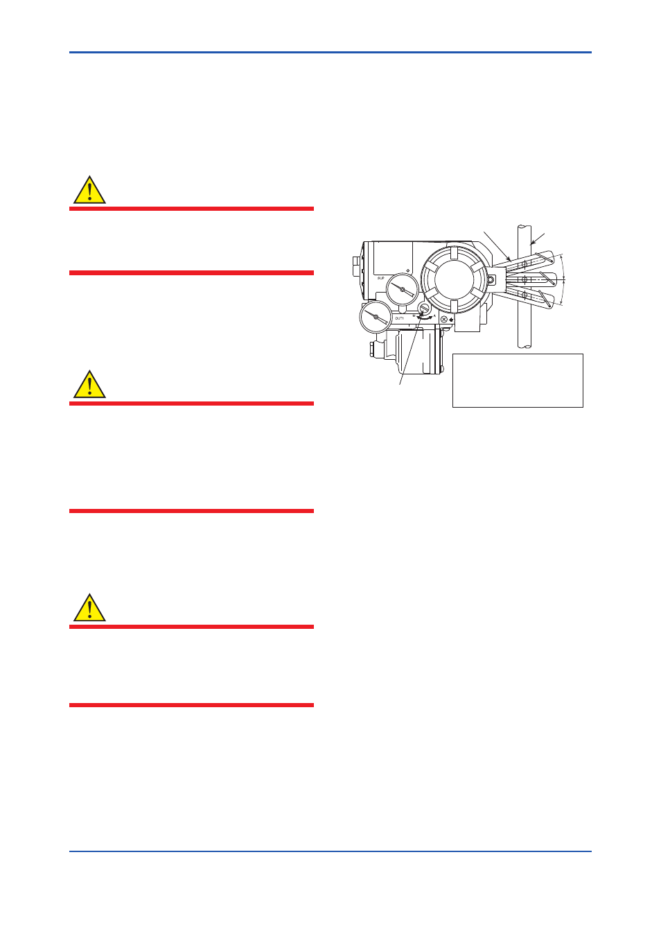
(3) Check that the feedback lever is at around the
horizontal level. If its incline deviates from the
horizontal level by 15 degrees or more, shut off
the air supply for safety. Then, after confirming
that the air has been completely exhausted out
of the actuator, readjust the clamp position.
(4) After the incline from the horizontal level has
been adjusted to within ±15 degrees, shut off
the air supply and turn the A/M selector switch
counterclockwise until it stops, to change the
selector position to A (automatic). (See also
Section 3.2.3, “A/M Switching”).
FA0501.ai
Valve stem
Lever
A/M selector switch
∆θ
The incline of lever from the
horizontal level ∆θ when the
stroke of the stem is 50% must
be: ∆θ ≤ ±15 degrees
Figure A5.1 Checking Position at Which Clamp
Should Be Fixed