Dimensions l for single acting actuator – Yokogawa YVP110 User Manual
Page 46
<7. Standard Specifications>
7-5
IM 21B04C01-01E
*1: Applicable for Connections code 3.
*2: Applicable for Connections code 3 and 6.
*3: Applicable for Connections code 1, 3 and 6.
*4: If cable wiring is to be used to a TIIS flameproof type transmitter, do not fail to add the YOKOGAWA assured flameproof packing
adapter.
*5:
Applicable for Option code EE.
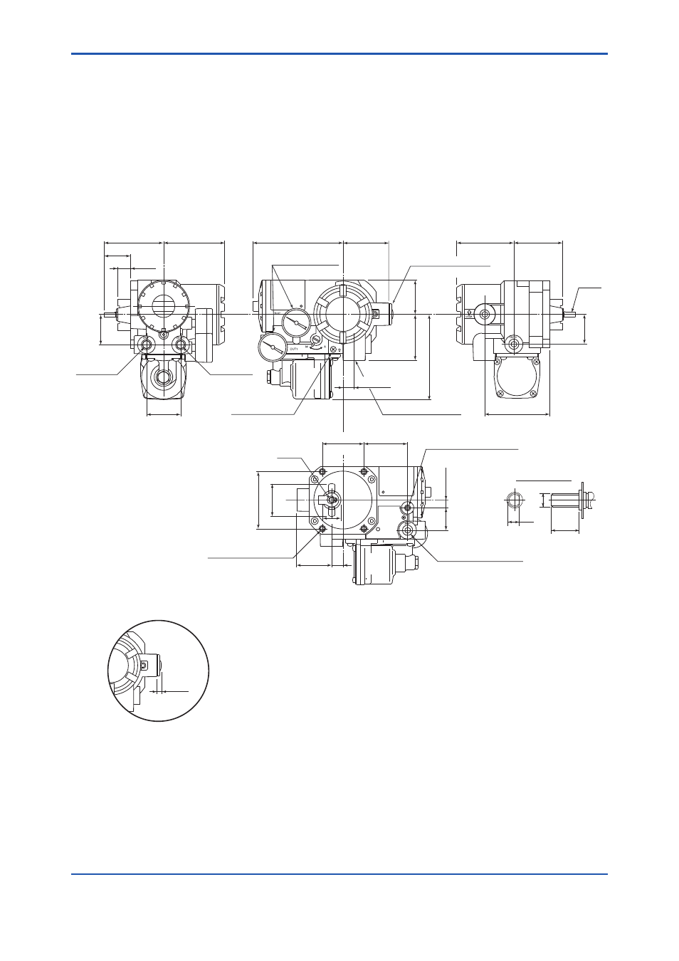
Dimensions
l
For Single Acting Actuator
Unit: mm(approx. inch)
F0701.ai
*2:
Attached with 4 mounting bolts (M8, 25 mm) and spring washers (applicable 3 to 6 mm thick brackets).
*3:
Available when unable to mount securely with the 4 bolts in *2.
5 to 6
(0.2 to 0.24)
*1:
Blind plug for Connection code 1, 5, and 6.
Details of shaft
5
12
ø6
85(3.3)
77(3.0)
80(3.1)
35
(1.3)
17
(0.7)
109(4.3)
45
(1.8)
60(2.4)
117(4.6)
76(3.0)
64(2.5)
44
(1.7)
60(2.4)
39 (1.5)
39 (1.5)
42 (1.6)
45
(1.8) 15
(0.6)
74(2.9)
54
(2.1)
57
(2.2)
10(0.4)
29
(1.1)
M8×1.25, 20(0.8)-deep
for Valve Mounting*
2
M8×1.25, 11(0.4)-deep
for Valve Mounting*
3
Out1
Connection
Pressure Gauge
(Optional)
Electrical Connection
Shaft
Shaft
Air Supply
Connection
Air Supply Connection
(with blind plug)
15(0.6)
Electrical Connection*
1
(with blind plug)
24
Ground Terminal