Setup, 1 general, 2 setting basic parameters – Yokogawa YVP110 User Manual
Page 34: Setup -1, General -1, Setting basic parameters -1, Caution, Important
<5. Setup>
5-1
IM 21B04C01-01E
5. Setup
CAUTION
During the setup especially when autotuning
is being executed, the valve stem may happen
to move suddenly to an unexpected direction.
Before starting the setup, check and confirm that
the process has been shut down or the control
valve is isolated from the process. During the
setup, keep away from the movable parts to
avoid injury.
5.1 General
After mechanically attaching the YVP110 to an
actuator and finishing the wiring and piping, connect
the YVP110 to a fieldbus and make settings, such
as carrying out auto tuning and setting the tight-shut
option, using a parameter setting tool or the like.
IMPORTANT
For the operation of a parameter setting tool,
read the manual of each tool. Also, read the
Chapters 8 through 10 and 12 of this manual
to become familiar with the configuration of
the fieldbus instrument and the function of the
transducer block before starting adjustment.
Check that the piping and wiring connections are
all correct, and then supply the specified input
voltage and air pressure. For the connection to
the fieldbus, see the chapters 4.3 'Wiring' and 8.4
'System Configuration'.
Parameter settings for the actuator and valve are to
be made in the parameters in the transducer block
inside the YVP110 positioner. For details of each
parameter, refer to the parameters list in Appendix
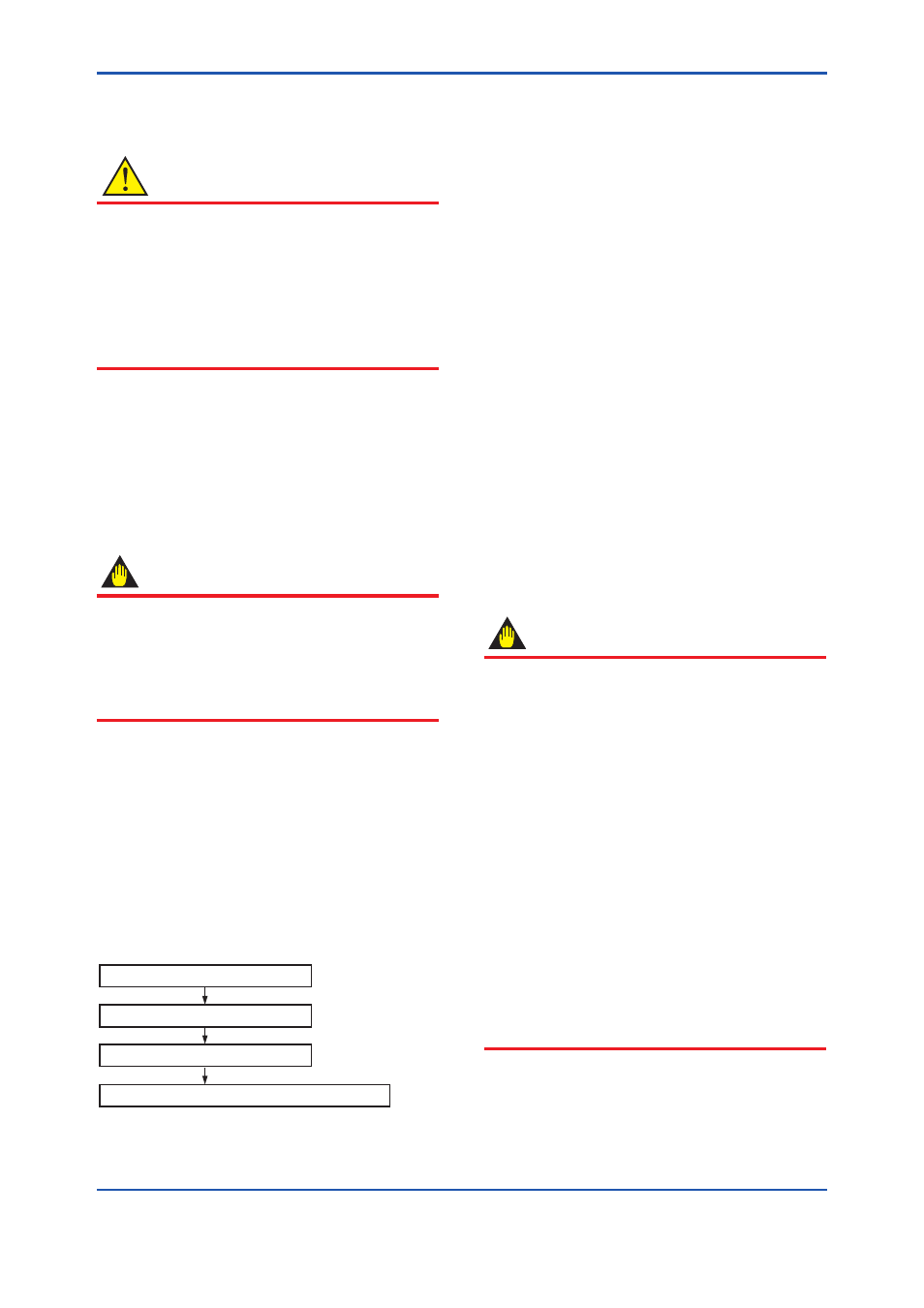
1. Follow the procedure below.
Set basic parameters (Section 5.2)
Carry out tuning (Section 5.3)
Check valve actions (Section 5.4)
Set transducer block's parameters (Section 5.5)
F0501.ai
Figure 5.1
Setup Procedure
5.2 Setting Basic Parameters
First, set the target mode's in the parameters
MODE_BLK of the transducer block and AO
function block to O/S (Out of Service). When either
one or both of the transducer block and AO function
block are in the O/S mode, the transducer block's
parameters that determine the valve actions are
write-locked.
(1) Selecting the Acting Direction of Valve
In the parameter ACT_FAIL_ACTION, set
the value, 1 or 2, corresponding to the acting
direction of the valve, whether the valve opens
or closes due to an increase of the pneumatic
pressure. The setting in ACT_FAIL_ACTION
determines the relationship between the
pneumatic input signal and 0-100% of the
valve position, where the 0% position means
complete closure.
1 = air to open
2 = air to close
IMPORTANT
For the transducer block, the 0% output always
means complete closure of the valve. Set
ACT_FAIL_ACTION correctly in accordance
with the acting direction of the valve used.
Nonetheless, the 0-100% of the transducer
block's output can be logically reversed by setting
IO_OPTS in the AO block to true.
Independently of the above setting, YVP110
always acts identical upon power off and cut-off
of the air supply.
When a power failure or serious hardware
damage is detected, the YVP110 cuts the
current signal being fed to the I/P module to
zero, moving the valve to the safe side. The
action of the YVP110 upon occurrence of a
communication error can be predefined by AO
block’s parameters; see Section 13.3.1, “Fault
State.”