Appendix 6. manual tuning guideline, A6.1 general, A6.2 control parameter tuning procedure – Yokogawa YVP110 User Manual
Page 149: A6.1, A6.2, A-38
A-38
IM 21B04C01-01E
Appendix 6. Manual Tuning Guideline
A6.1 General
The YVP110 can improve controllability by properly
performing the manual tuning of control parameters
for each valve and actuator.
The following shows the whole tuning procedure.
Manual Tuning
(Manually adjust control parameters)
Check value
actions (5.4)
Carry out Auto Tuning (5.3)
(Adjust zero-point and span,
and set control parameters)
Successful?
Yes
No
NG
Adjust zero-point and span at fully
closed/opened positions (5.3, 12.4)
and travel calibration (5.3, 12.5)
Set basic parameters (5.2)
Set transducer block’s parameters (5.5)
Good
FA0601.ai
If you cannot obtain expected response
characteristics by Auto Tuning, verify the 10% step
response and compare your response waveform
with three types of response waveforms shown
in A6.2. Adjust parameters by referring to the
procedure of a waveform that has characteristics
similar to those of your waveform.
If Auto Tuning fails, adjust the zero-point and
the span, then set the parameters by referring
to the default settings (factory settings) or tuning
examples in A6.3. Then verify the 10% step
response and adjust the parameters according to
the procedure described in A6.2.
(For detail about the control parameters, see
section A6.4.)
Before carrying out parameter tuning, change the
modes of the AO function block and transducer
block to O/S.
A6.2 Control Parameter Tuning
Procedure
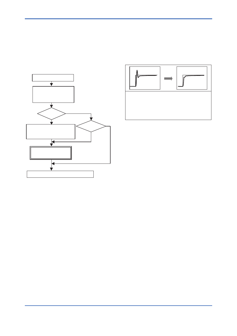
[1] Fast response
[Characteristics]
Since both the rise and tracking of the target value are fast,
a V-shaped overshoot occurs. You can obtain a better
response by maintaining the response speed and reducing
overshoot.
This waveform is typically observed in small capacity
actuators.
FA0602.ai
(1) Modifying overshoot
• Increase the value for SERVO_RATE to reduce
an excessively rapid response. Verify the 10%
step response and increment the value by 0.2.
• If a significant improvement effect cannot be
obtained by only incrementing the value for
SERVO_RATE in small steps of approximately
5% or less, input the value in small steps in
BOOST_ON_THRESHOLD [2] and decrement
the value for BOOST_VALUE [1] by 2 to
decrease the boost.
• The same boost value is set on both the air
delivery and exhaust sides using Auto Tuning. If
the overshoot on the exhaust side is larger than
that on the air delivery side for a double-acting
model, input a negative value in
X_BOOST_VALUE[1][2], without changing the
value of 0 in
X_BST_ON_THRESHOLD[1][2] and
X_BST_OFF_THRESHOLD[1][2]. First, try to
input a negative value of half that of BOOST_
VALUE [1] [2], and if necessary, increment or
decrement the value by 1.
• If necessary, increment or decrement the value
for SERVO_GAIN by 30.
(2) Improving the stabilization time
Decrease the value for SERVO_RESET to improve
the capability of tracking the target value. Verify the
10% step response and decrement the value by 3.