2 installing yvp110 on rotary-motion control valve, Caution, Important – Yokogawa YVP110 User Manual
Page 27
<3. Installing YVP110 on Actuator>
3-3
IM 21B04C01-01E
CAUTION
It is extremely likely that attaching the lever in the
wrong orientation will cause the feedback shaft
to rotate at an angle exceeding its mechanical
limits of ±55 degrees, resulting in the YVP110
being seriously damaged.
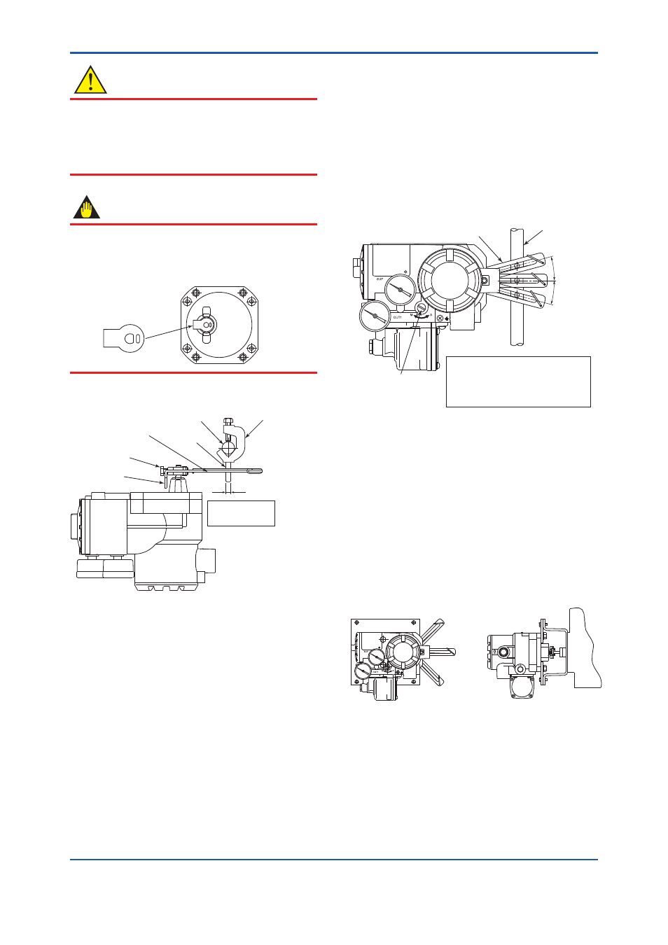
IMPORTANT
A stopper is attached to the feedback shaft to
prevent an over-rotation of the shaft as shown
below. When installing the lever, make sure that
you install it on the stopper.
F0311.ai
Stopper
Next, fix the lock screw.
Feedback lever
Valve stem
Clamp pin
Lock screw
Applicable pin
O.D.: 6 mm
Stopper
Clamp
F0305.ai
Figure 3.5
Attaching Lever and Clamp
(2) Attach the clamp to the stem in reference with
Figure 3.5. It is necessary to set the clamp
of the YVP110 in a position that allows the
feedback lever to be at an angle within ±15
degrees from the horizontal level when the
valve stem is at the 50% position (see Figure
3.6). Installing the YVP110 at a carefully
determined position, where the feedback lever
is at the horizontal level when the valve stem is
at the 50% position, will make the consequent
installation work easier.
Note that only if the YVP110 is installed at a
position meeting the specification above, it is
guaranteed that the specified accuracy can
be obtained by linearity correction (see also
Section 13.5, “Travel Calibration”).
When using the Single Acting Type, it is
possible to adjust the position of the feedback
lever while air is being supplied to the actuator.
See Appendix 5. “POSITION ADJUSTMENT
OF FEEDBACK LEVER”.
F0306.ai
The incline of lever from the
horizontal level ∆θ when the stroke
of the stem is 50% must be:
∆θ ≤ ±15 degrees
A/M selector switch
Valve stem
Lever
∆θ
Figure 3.6
Checking Position at Which Clamp
Should Be Fixed
3.2.2 Installing YVP110 on Rotary-motion
Control Valve
The following shows the general installation
procedure when assembling a YVP110 with
a rotary-motion control valve combined with a
diaphragm actuator or cylinder actuator. Note that
the most suitable procedure may differ depending
on the shapes of the bracket and valve actuator,
and the structure of the actuator.
F0307.ai
Figure 3.7
YVP Installed on Rotary-motion Valve/
Actuator