Yokogawa YVP110 User Manual
Page 26
<3. Installing YVP110 on Actuator>
3-2
IM 21B04C01-01E
(2) Fixing the YVP110 to Actuator with Bracket
After fixing the bracket to the YVP110, attach it
to the actuator with the specified bolts.
Depending on the shapes of the bracket and
actuator, the working space at the rear of the
YVP110 where the feedback shaft is positioned
may be quite narrow, making installation work
tricky. In such a case, the entire procedure
may be made much easier by attaching
the feedback lever to the feedback shaft as
described in step (3), prior to carrying out step
(2). Check the space behind the YVP110
beforehand.
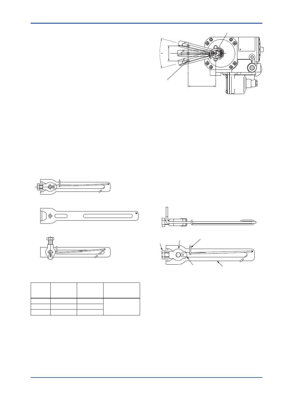
(3) Attaching Feedback Lever
The YVP110 with option code /LV1 comes with
two different feedback levers, (1) and (2) shown
below, and the one with option code /LV2
comes with lever (3). Check the specifications
of the levers shown in Table 3.1 and Figure
3.2 and choose the lever most suitable for the
control valve used.
F0302.ai
(1) F9176HA
(2) F9176HC
(3) F9176HD
Figure 3.2
Feedback Levers
Table 3.1
Specifications of Levers
Lever
Model
Stroke (X)
Pin-to-shaft
Distance (L)
Allowable Range of
Rotation Angle of
Feedback Shaft(θ)
F9176HA 10 to 60 mm
25 to 75 mm
±10 to 25 degrees
F9176HC 30 to 100 mm 75 to 115 mm
F9176HD 5 to 20 mm
14 to 20 mm
Note: When assembling a YVP110 with a linear-motion actuator,
ensure that the rotation angle of the YVP110’s feedback
shaft does not exceed the allowable range (10 to 25
degrees shown above.
Only if the range of the rotation angle is within this
specification, it is guaranteed that the specified accuracy
can be obtained by linearity correction (see the description
for travel calibration in Section 5.3, “Carrying out Auto
Tuning”).
F0303.ai
L
X
θ
Feedback shaft
Clamp pin
on side of valve
SUP
Figure 3.3
Stroke of Lever
When /LV1 is specified, the hardware for attaching
the lever to the feedback shaft and the spring for
fixing the clamp pin are attached to the F9176HA,
the smaller feedback lever for generally used
mid-capacity actuators. Thus, when using the
F9176HC, the feedback lever for high-capacity
actuators, detach and use the hardware and spring
from the F9176HA. See Figure 3.4. To do so, first
detach the spring <4>. Then, detach the clip <1>
and remove the hardware <2> and <3>. Attach <1>
to <4> to the F9176HC feedback lever for high-
capacity actuators in the reverse order.
The hardware and the spring attached to the /LV2
lever is not compatible with those for the /LV1 lever.
F0304.ai
<3>
<2>
<4>
<1>
Lever
Figure 3.4
Disassembling a Lever Assembly
When determining which lever to use, follow the
procedure below to make a linkage between the
YVP110 positioner and control valve’s stem via the
clamp and lever. The adjustment of this linkage is
a decisive factor for determining the characteristics
of the control valve combined with the YVP110
positioner.
(1) Insert the YVP110’s feedback shaft into the
small hole on the stopper side of the lever as
shown in Figure 3.5.