1 connection of devices, 5 integration of dd, Connection of devices -2 – Yokogawa YVP110 User Manual
Page 50: Integration of dd -2, Important
<8. About Fieldbus>
8-2
IM 21B04C01-01E
• Power supply:
Fieldbus requires a dedicated power supply. It
is recommended that current capacity be well
over the total value of the maximum current
consumed by all devices (including the host).
Conventional DC current cannot be used as is.
• Terminator:
Fieldbus requires two terminators. Refer to
the supplier for details of terminators that are
attached to the host.
• Field devices:
Connect the field devices necessary for
instrumentation. YVP110 has passed the
interoperability test conducted by The Fieldbus
Foundation. In order to properly start Fieldbus,
it is recommended that the devices used satisfy
the requirements of the above test.
• Host:
Used for accessing field devices. A
dedicated host (such as DCS) is used for
an instrumentation line while dedicated
communication tools are used for experimental
purposes.
• Cable:
Used for connecting devices. Refer to “Fieldbus
Technical Information” (TI 38K3A01-01E) for
details of instrumentation cabling. Provide a
cable sufficiently long to connect all devices.
For field branch cabling, use terminal boards
or a connection box as required. If the total
length of the cable is in a range of 2 to 3 meters
for laboratory or other experimental use, the
following simplified cable (a twisted pair wire
with a cross section of 0.9 mm
2
or more (AWG
#18) and cycle period of within 5 cm (2 inches)
may be used. Termination processing depends
on the type of device being deployed. For
YVP110, use an M4 screw terminal claw. Some
hosts require a connector.
Refer to Yokogawa when making arrangements to
purchase the recommended equipment.
The number of devices that can be connected to
a single bus and the cable length vary depending
on system design. When constructing systems,
both the basic and overall design must be carefully
considered to allow device performance to be fully
exhibited.
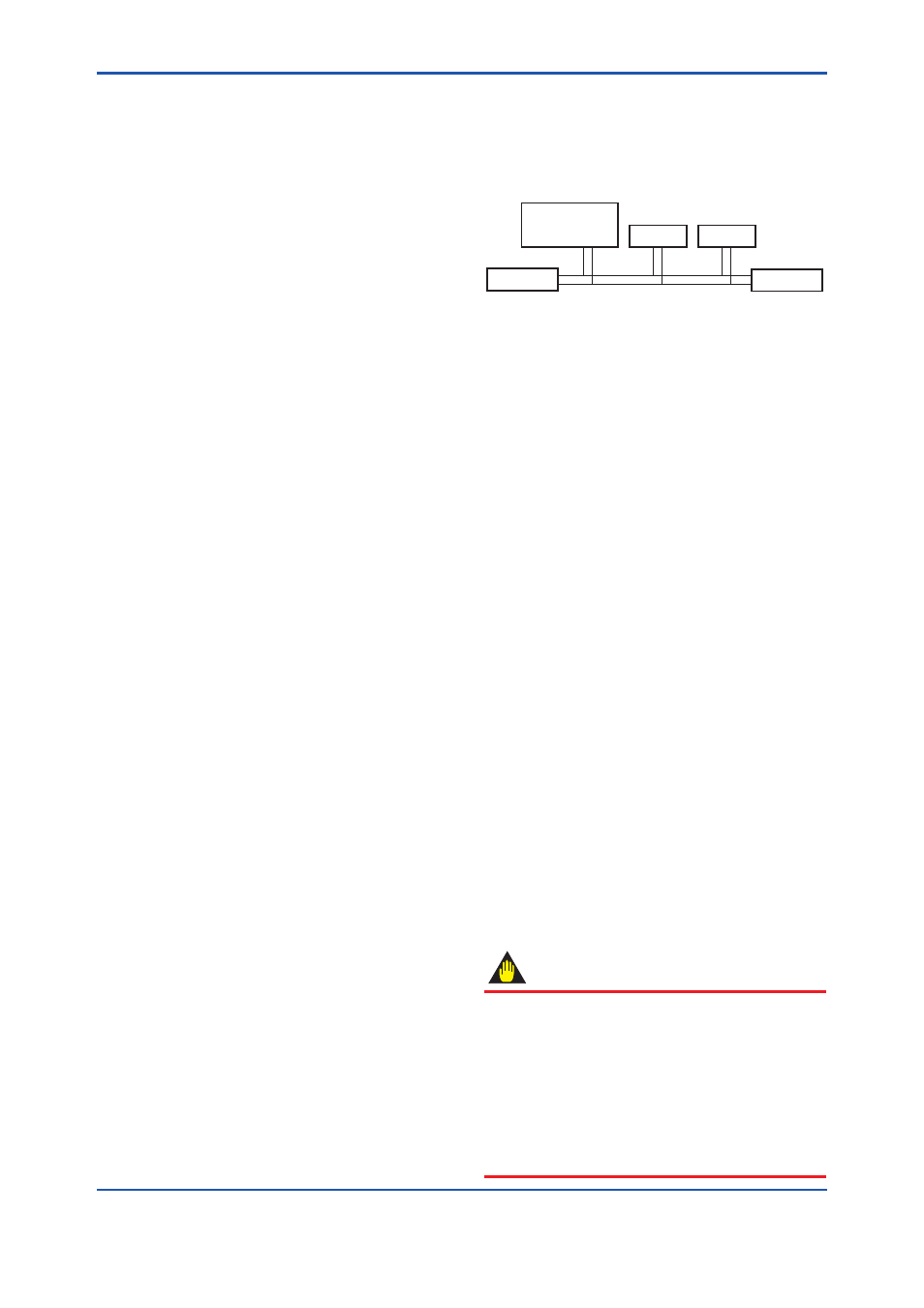
8.4.1 Connection of Devices
Connect the devices as shown in Figure 9.1.
Connect the terminators at both ends of the
trunk, with a minimum length of the spur laid for
connection.
The polarity of signal and power must be
maintained.
YVP110
Fieldbus power
supply
Terminator
Terminator
HOST
F0802.ai
Figure 8.2
Cabling
Before using a Fieldbus configuration tool other
than the existing host, confirm it does not affect the
loop functionality in which all devices are already
installed in operation. Disconnect the relevant
control loop from the bus if necessary.
8.5 Integration of DD
If the host supports DD (Device Description), the
DD of the YVP110 needs to be installed. Check if
host has the following directory under its default DD
directory.
594543/0001
594543/0007 (/EE)
(594543 is the manufacturer number of
Yokogawa Electric Corporation, and 0001
or 0007 is the YVP110 device number,
respectively.)
If this directory is not found, DD of YVP110 has not
been included. Create the above directory and copy
the DD file (0m0n.ffo,0m0n.sym) (m, n is a numeral)
into the directory.
Once the DD is installed in the directory, the name
and attribute of all parameters of the YVP110 are
displayed.
Off-line configuration is allowed by using the
capability file (CFF). If you do not have the DD or
capability file for the YVP110, you can download it
from www.yokogawa.com/fld/
IMPORTANT
For offline configuration, use the CFF which
matches the specification of the instrument to be
configured. For YVP110, there are three types
of CFF file; one for standard type instruments,
second for the instruments with one or two PID
function blocks are available and the other can
be selected between former two types using
capability level description. Using unmatched
CFF will cause an error upon downloads, etc.