4 setting of tags and addresses, Setting of tags and addresses -3 – Yokogawa YVP110 User Manual
Page 53
<9. Configuration>
9-3
IM 21B04C01-01E
Table 9.3
Execution Schedule of the YVP110
Function Blocks
Index
Parameters
Setting (Enclosed is
factory-setting)
269
(SM)
MACROCYCLE_
DURATION
Cycle (MACROCYCLE)
period of control or
measurement. Unit is 1/32
ms. (32000 = 1 s)
276
(SM)
FB_START_
ENTRY.1
AO block startup time.
Elapsed time from the
start of MACROCYCLE
specified in 1/32 ms.
(32000 = 1 s)
278
(SM)
FB_START_
ENTRY.2
—
..
.
289
(SM)
FB_START_
ENTRY.14
—
Table 9.4 shows maximum execution time of YVP
function blocks.
Table 9.4
Execution Time of YVP Function Blocks
Block
Name
Execution
time (ms)
Remarks
AO
95
DI
40
PID
120
Available for option /LC1 or /LC2
OS
95
IS
140
Available for option /EE
AR
120
Available for option /EE
For scheduling of communications for combination
with the next function block, the execution is so
arranged as to start after a lapse of longer than
the time above mentioned. In no case should two
function blocks of the YVP110 be executed at the
same time (execution time is overlapped).
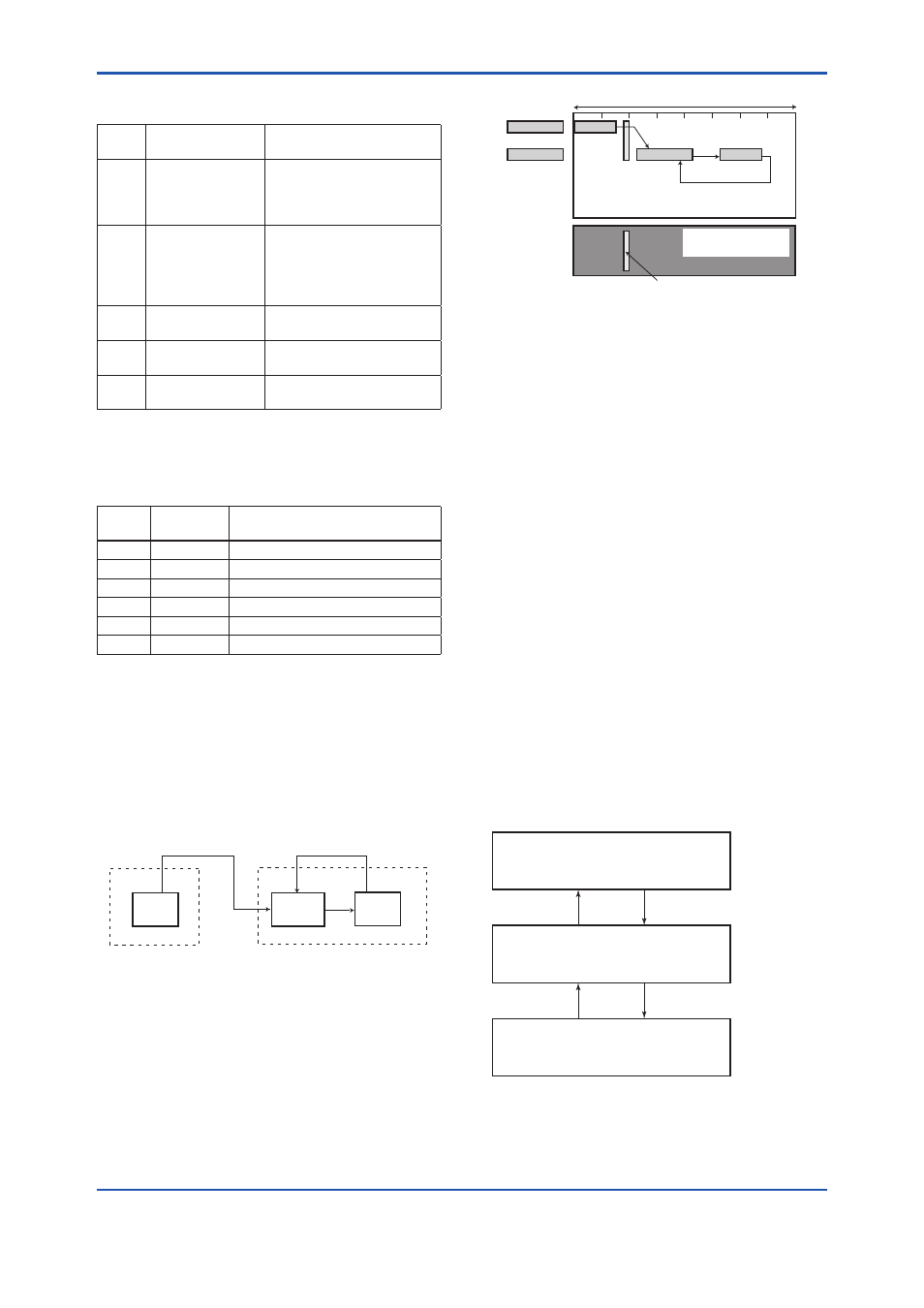
Figure 9.3 shows an example of schedule based on
the loop shown in Figure 9.2.
F902.ai
PID
YVP110
Advanced
Valve Positioner
AI
EJA110
Differential Pressure
Transmitter
AO
Figure 9.2
Example of Loop Connecting Function
Block of YVP110 with other instruments
EJA110
AI
YVP110
PID
AO
Function
Block
Schedule
Communication
Schedule
IN
BKCAL_IN
BKCAL_OUT
F0903.ai
OUT
Unscheduled
Communication
Scheduled Communication
Macrocycle (Control Period)
OUT CAS_IN
Figure 9.3
Function Block Schedule and
Communication Schedule
For the case where the control period(macrocycle)
is set to 4 seconds or longer, set the following
interval larger than 1% of the macrocycle.
• The interval between 'the end of block
execution' and 'the start of releasing CD from
LAS'.
• The interval between 'the end of a block
execution' and 'the start of the next block
execution'.
9.4 Setting of Tags and
Addresses
This section describes the steps in the procedure
to set PD Tags and node addresses in the YVP110.
Connect YVP110 with other network devices and
turn on the power of the host and the bus.
There are three states of Fieldbus devices as
shown in Figure 9.4, and if the state is other than
the lowest SM_OPERATIONAL state, no function
block is executed. YVP110 must be transferred to
this state when a tag or address is changed.
UNINITIALIZED
(No tag nor address is set)
Tag clear
Tag setting
INITIALIZED
(Only tag is set)
SM_OPERATIONAL
(Tag and address are retained, and
the function block can be executed.)
Address clear
F0904.ai
Address setting
Figure 9.4
Status Transition by Setting PD Tag and
Node Address