IAI America PCON-CFA User Manual
Page 48
3.
ACON-C/CG, PCON-C/CG
CC-Link
42
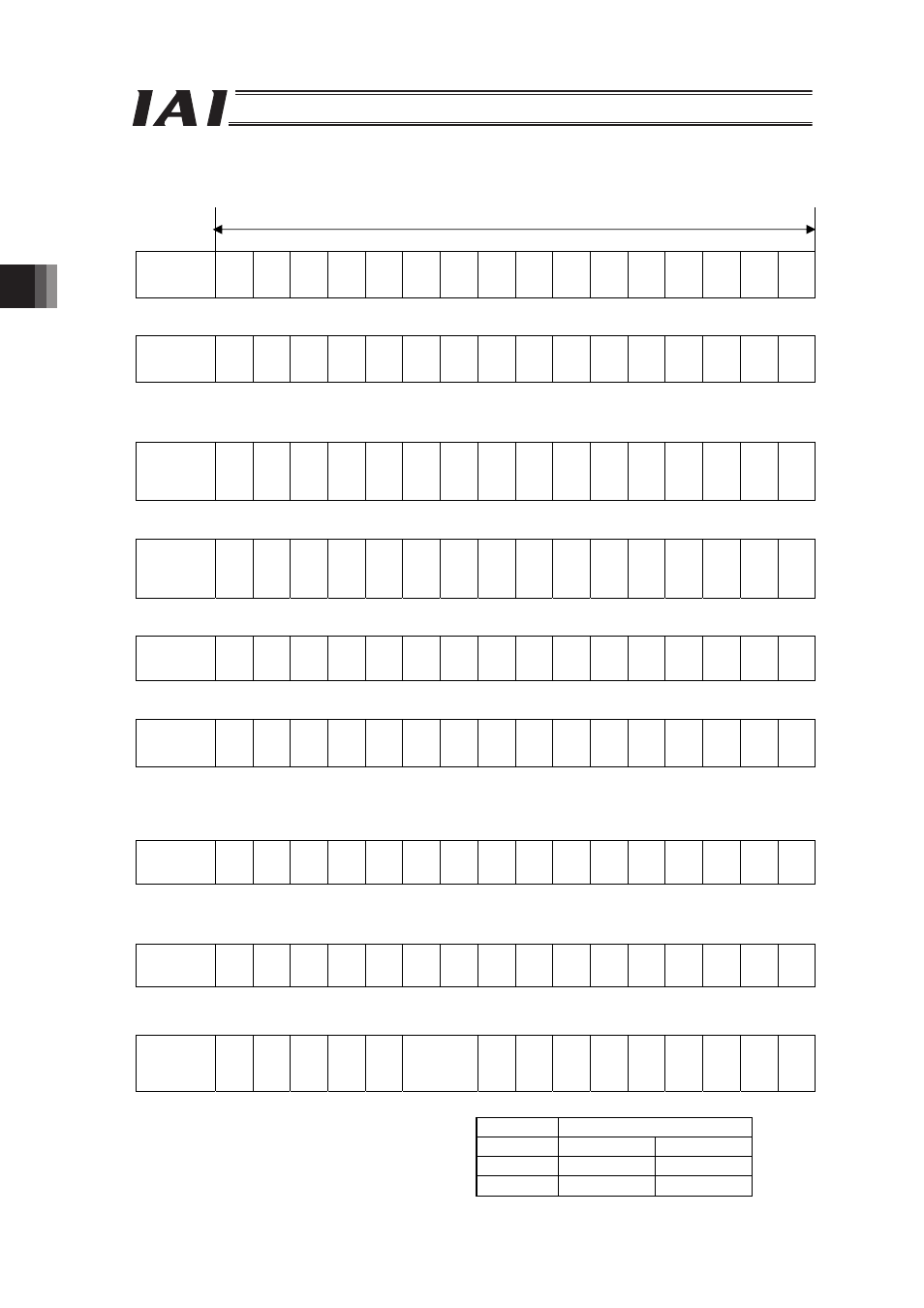
PLC Input
Address (* “n” shows the head register address per each axis).
one word = 16 bits
RWr (n+0) b15 b14 b13 b12 b11 b10 b9
b8
b7
b6
b5
b4 b3 b2 b1
b0
Current Position
(Slave Word)
RWr (n+1) b15 b14 b13 b12 b11 b10 b9
b8
b7
b6
b5
b4 b3 b2 b1
b0
Current Position
(Host Word)
When the current position is shown using the negative figure, it is expressed using the complement of 2.
RWr (n+2) b15 b14 b13 b12 b11 b10 b9
b8
b7
b6
b5
b4 b3 b2 b1
b0
Command
Current
(Slave Word)
32
,7
68
16
,3
84
8,
19
2
4,
09
6
2,
04
8
1,
02
4
51
2
25
6
12
8
64
32
16
8
4
2
1
RWr (n+3) b15 b14 b13 b12 b11 b10 b9
b8
b7
b6
b5
b4 b3 b2 b1
b0
Command
Current
(Host Word)
52
4,
28
8
26
2,
14
4
13
1,
07
2
65
,5
36
RWr (n+4) b15 b14 b13 b12 b11 b10 b9
b8
b7
b6
b5
b4 b3 b2 b1
b0
Current Speed
(Slave Word)
RWr (n+5) b15 b14 b13 b12 b11 b10 b9
b8
b7
b6
b5
b4 b3 b2 b1
b0
Current Speed
(Host Word)
When the Current Speed is shown using the negative figure, it is expressed using the complement of 2.
RWr (n+6) b15 b14 b13 b12 b11 b10 b9
b8
b7
b6
b5
b4 b3 b2 b1
b0
Alarm
code
RWr (n+7) to
RWr (n+F)
b15 b14 b13 b12 b11 b10 b9
b8
b7
b6
b5
b4 b3 b2 b1
b0
Unavailable
RWr (n+F) b15 b14 b13 b12 b11 b10 b9
b8
b7
b6
b5
b4 b3 b2 b1
b0
Status
Signal
EMGS
P
W
R
ZONE2
ZONE1
PZONE
(*
1)
R
M
D
S
GHMS
P
U
S
H
P
S
FL
SV
A
LM
MOVE
H
EN
D
P
E
N
D
(*1) RWr (n+F) b10 and b9 Signal Allocation
Symbol
Controller
ACON
PCON
b10
LOAD
b9
TRQS