Extron Electronics HDXP Plus Series User Guide User Manual
Page 63
HDXP Plus Series Switchers • Remote Configuration and Control
57
Command
ASCII Command
(Host to Switcher)
Response
(Switcher to Host)
Additional Description
View Ties and Presets (continued)
View global video preset
E
X1!
*
X#
*1VC
}
X@
•
X@
•...•
X@
• Vid
]
Show preset
X1!
video
configuration. Show the input
(
X@
) tied to 16 sequential
outputs, starting with
output
X#
.
NOTES:
•
For HDXP 1616 and HDXP 3216, the starting output number is 1.
•
To view the current video configuration, enter
E
0*
X#
* 1VC
}
.
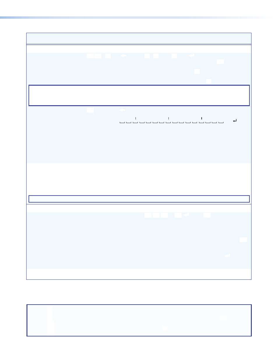
Example: HDXP 3232
E
4 * 17 * 1VC
}
See below.
17
Output:
Response = tied input:
Input 24 tied to output 19
18 19 20 21 22 23 24 25 26 27 28
08•08•24•08•08•29•29•00•08•01•01•01•08•08•08•08•Vid
29 30 31 32
No tied input
Input 8 tied to output 29
Each position shown in the response is an output. The first position on the left is the
starting output and the last position (first position on the right) is the starting output number
plus 15 (16 on the HDXP 1616 and 3216). The number in each position is the input tied to
that output.
In this example (preset 4) input 1 is tied to outputs 26 through 28. Input 8 is tied to outputs
17, 18, 20,21, 25, and 29 through 32. Input 24 is tied to output 19 and input 29 is tied to
outputs 22 and 23. No input is tied to output 24.
View video room preset
E
X*
*
X1@
*
X#
*1VC
}
X@
•
X@
•...•
X@
• Vid
]
Show room
X*
, preset
X1@
video configuration. Show the
input (
X@
) tied to 16 sequential
outputs assigned to room
X*
,
starting from output
X#
.
NOTE: For the HDXP 1616 and 3216, the starting output number is
1.
List Digital Sync Validation Processing (DSVP)
List available input signals
0LS
X2!
X2!
X2!
...
X2!
n
]
Each
X2!
response indicates
presence or absence of
horizontal and vertical sync on
an input, starting from input 1.
n is the maximum number of
inputs on your model. For
X2!
:
0 = no signal
1 = signal present
Example: HDXP 3232
0LS
00000010000000001000000001000010
]
Inputs 7, 17, 26, and 31 have
signals.
List individual signal status
X@
LS
X2!
]
Show signal status
X2!
for input
X@
.
NOTE:
X@
= Input number (for ties)
0 – maximum number of inputs for your model (0 = untied)
X#
= Output number
1 – maximum number of outputs for your model
X*
= Room number (for room presets)
1 – 10. Each room can have up to 10 room presets (
X1@
) assigned.
X1!
= Global preset number
00 – 32. 00 = current configuration
X1@
= Room preset number
1 – 10. Each room (
X*
) can have up to 10 presets assigned.
X2!
= Signal status, DVSP
1 = signal present at input, 0 = no signal at input