Symbol definitions, Using the command and response table, For sis commands – Extron Electronics HDXP Plus Series User Guide User Manual
Page 55
HDXP Plus Series Switchers • Remote Configuration and Control
49
Using the Command and Response Table for SIS Commands
The
begins on page 54. Lowercase letters are
acceptable in the command field except where indicated. The table below shows the
hexadecimal equivalent of each ASCII character used in the command and response
table.
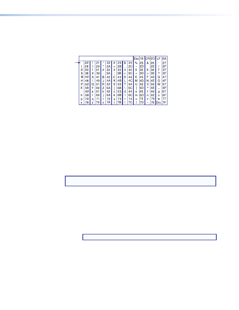
ASCII to Hex Conversion Table
•
Space
Figure 67.
ASCII to Hexadecimal Conversion
Symbols are used throughout the table to represent variables in the command and
response fields. Command and response examples are shown throughout the table.
Symbol Definitions
]
= Carriage return and line feed
}
= Carriage return (no line feed)
|
= Pipe character (alternative for carriage return, no line feed)
•
= Space
E
=
W
= Alternative for
NOTE: Input and output numbers in commands can be entered as 1-digit, 2-digit, or 3-digit
numbers. All input and output numbers are reported as 2-digit numbers in the response.
24, 27, 28
= E24, E27, and E28 error codes. These superscripts indicate the error message
displayed if the command is entered incorrectly or with invalid parameters (see
X!
= Input number
HDXP 1616: 1 – 16
HDXP 3216 and 3232: 1 – 32
X@
= Input number (for tie)
HDXP 1616: 0 – 16
HDXP 3216 and 3232: 0 – 32
NOTE: Input
0 = muted input
X#
= Output number
HDXP 1616 and 3216: 01 – 17
HDXP 3232: 01 – 33
X%
= Output reclocking rate
00 = Auto (default)
03 = 177 (component PAL)
06 = 540
01 = Bypass
04 = 270
07 = 1485
02 = 143 (component NTSC)
05 = 360
08 = 2970
X^
=
Total inputs in the matrix
X&
= Total outputs in the matrix