Ethernet connection – Extron Electronics HDXP Plus Series User Guide User Manual
Page 16
HDXP Plus Series Switchers • Installation
10
Ethernet Connection
f
LAN port — If desired, connect the HDXP switcher to a PC or to an Ethernet LAN
via this RJ-45 connector. Use a PC to control the networked switcher with SIS
commands (see the
Remote Configuration and Control
section, beginning on
page 45), the windows-based control program (see the
section,
beginning on page 67), or the HTML pages (see the
section, beginning on page 96).
Ethernet connection indicators — The Link and Act LEDs indicate the
status of the Ethernet connection. The Link LED indicates that the switcher
is properly connected to an Ethernet LAN. This LED should light steadily.
The Act LED indicates transmission of data packets on the RJ-45 connector.
This LED should flicker as the switcher communicates.
Cabling and RJ-45 connector wiring
It is vital that you use the correct Ethernet cables, and that they be properly
terminated with the correct pinout. Ethernet links use Category (CAT) 5e or CAT 6,
unshielded twisted pair (UTP) or shielded twisted pair (STP) cables, terminated with
RJ-45 connectors. Ethernet cables are limited to a length of 328 feet (100 m).
NOTES:
•
Do not use standard telephone cables. Telephone cables do not support
Ethernet or Fast Ethernet.
•
Do not stretch or bend cables. Transmission errors can occur.
The Ethernet cable must be properly terminated for your application as either a
crossover or a straight-through cable.
•
Crossover cable — Direct connection between the computer and the
HDXP switcher.
•
Patch (straight) cable — Connection of the HDXP to an Ethernet LAN.
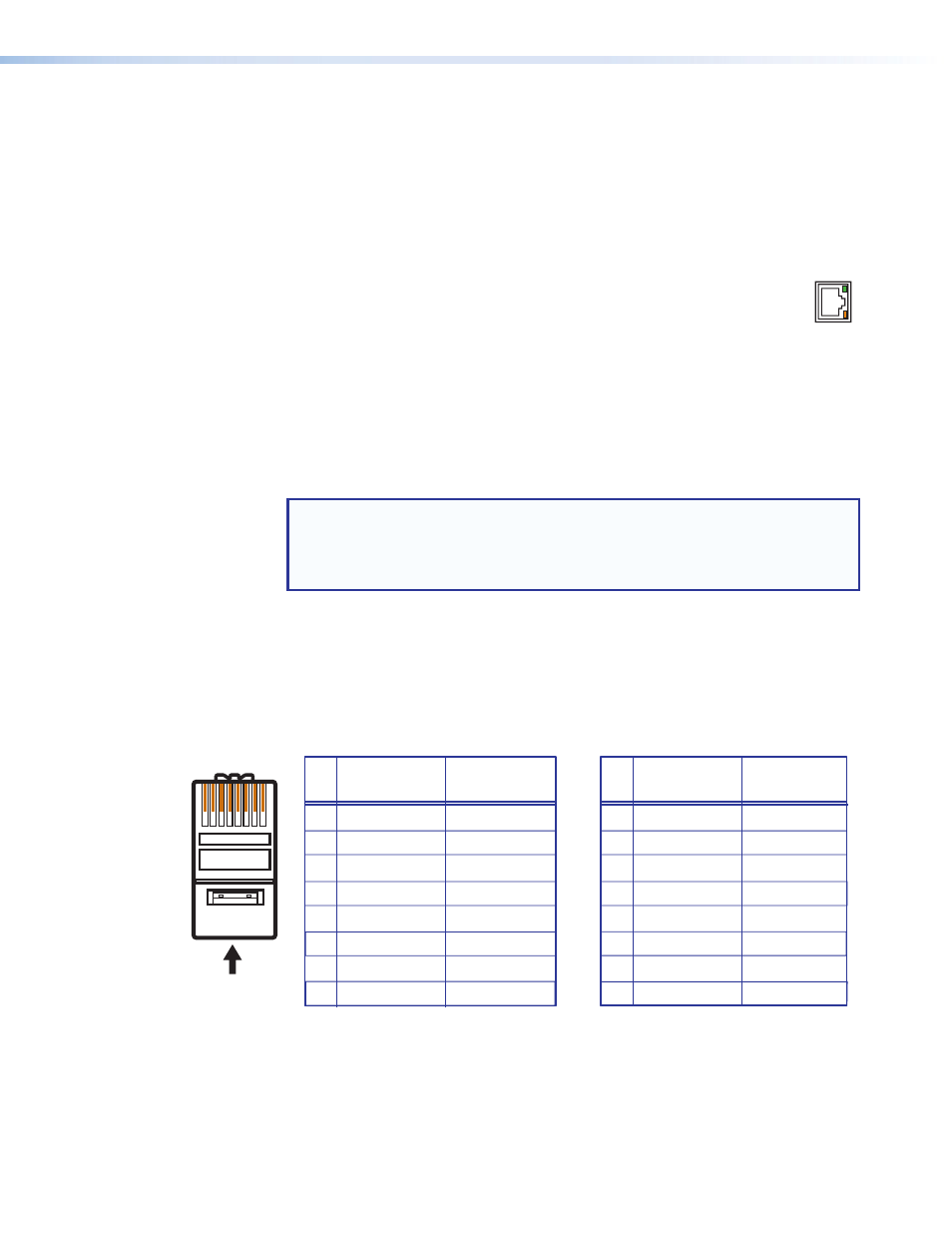
A cable that is wired as T568A at one end
and T568B at the other (Tx and Rx pairs
reversed) is a "crossover" cable.
A cable that is wired the same at both ends
is called a "straight-through" cable because
no pin or pair assignments are swapped.
Both ends of the cable can be T568B
(as shown) or T568A (not shown).
RJ-45
Connector
Insert Twisted
Pair Wires
1 2 3 4 5 6 7 8
Pins:
Crossover Cable
Straight-through Cable
Pin
1
2
3
4
5
6
7
8
Wire Color
White-green
Green
White-orange
Blue
White-blue
Orange
White-brown
Brown
Wire Color
T568A
T568B
End 1
End 2
End 1
End 2
White-orange
Orange
White-green
Blue
White-blue
Green
White-brown
Brown
Pin
1
2
3
4
5
6
7
8
Wire Color
Blue
White-blue
White-brown
Brown
Wire Color
T568B
T568B
White-orange
White-orange
Orange
Orange
White-green
White-green
Blue
White-blue
Green
Green
White-brown
Brown
Figure 7.
RJ-45 Connector and Pinout Tables
AC
T
LINK
LAN