Lift – Juniper Networks MX480 User Manual
Page 94
to the router. The following procedures describe how to remove components from the
chassis, first from the rear and then from the front:
1.
Removing the Power Supplies Before Installing the MX480 Router with a
Lift on page 70
2.
Removing the Fan Tray Before Installing the MX480 Router with a Lift on page 71
3.
Removing the SCBs Before Installing the MX480 Router with a Lift on page 71
4.
Removing the DPCs Before Installing the MX480 Router with a Lift on page 72
5.
Removing the FPCs Before Installing the MX480 Router with a Lift on page 73
Removing the Power Supplies Before Installing the MX480 Router with a Lift
Remove the leftmost power supply first and then work your way to the right. To remove
the AC or DC power supplies for each power supply (see
):
1.
Attach an electrostatic discharge (ESD) grounding strap to your bare wrist, and connect
the strap to an approved site ESD grounding point. See the instructions for your site.
2.
On an AC-powered router, switch the AC input switch on each power supply to the
off (
O
) position. On a DC-powered router, Move the DC circuit breaker on each DC
power supply to the off (
O
) position.
We recommend this even though the power supplies are not connected to power
sources.
3.
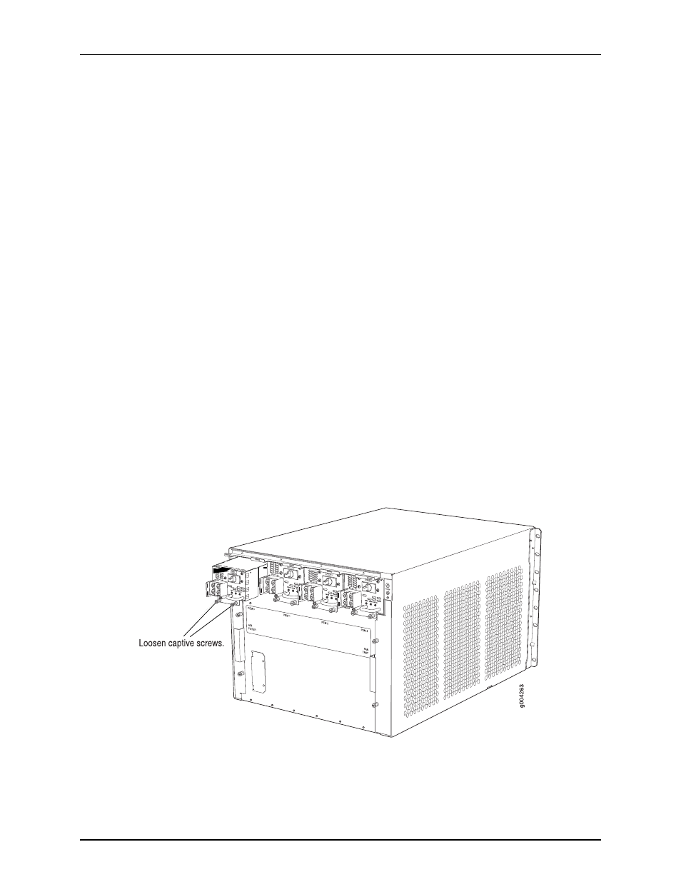
Loosen the captive screws on the bottom edge of the power supply faceplate.
4.
Pull the power supply straight out of the chassis.
Figure 36: Removing a Power Supply Before Installing the Router
Copyright © 2013, Juniper Networks, Inc.
70
MX480 3D Universal Edge Router Hardware Guide