Juniper Networks MX480 User Manual
Page 262
CAUTION:
The maximum torque rating of the terminal studs on the DC
power supply is 36 lb-in. (4.0 Nm). The terminal studs may be damaged
if excessive torque is applied. Use only a torque-controlled driver or socket
wrench to tighten nuts on the DC power supply terminal studs.
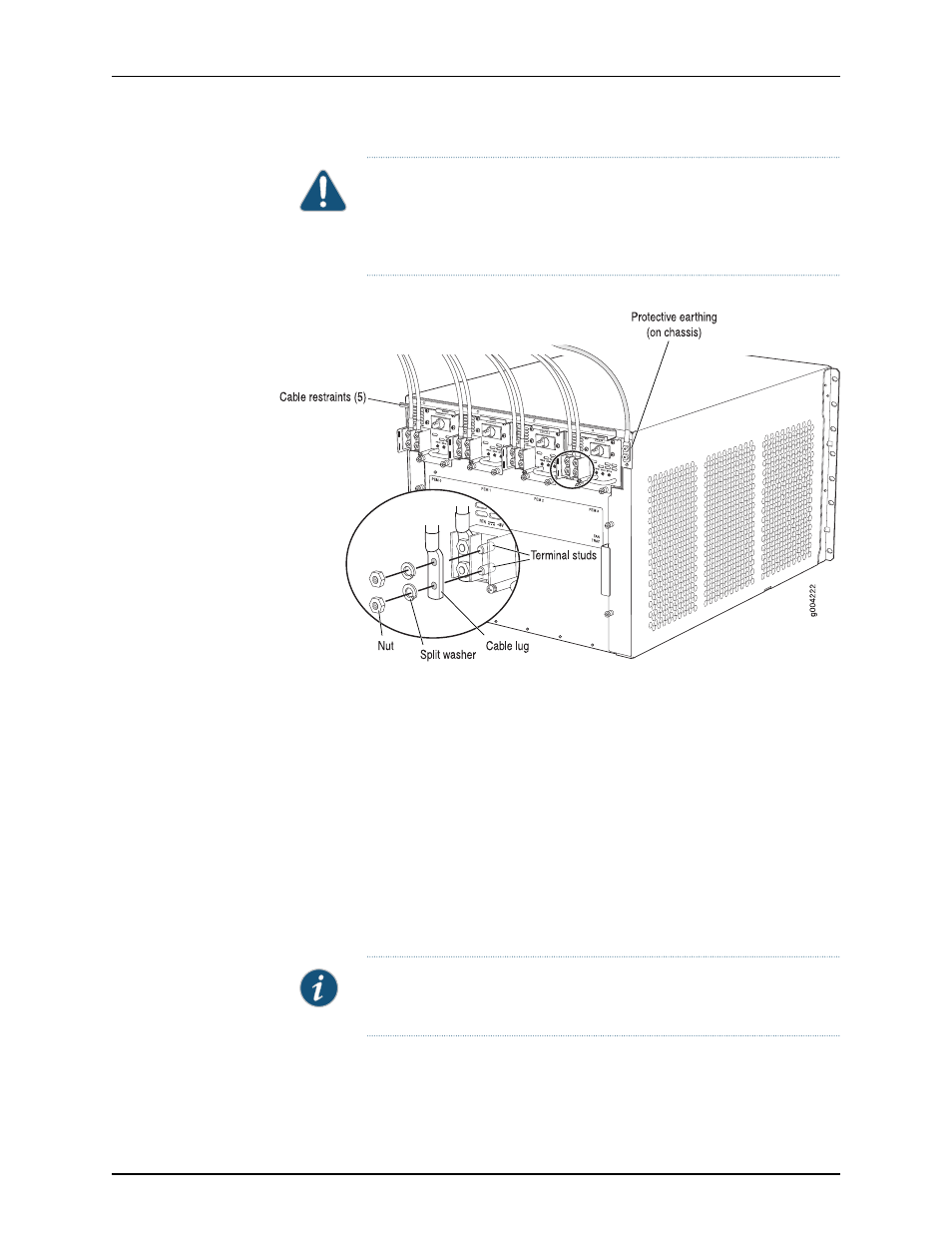
Figure 123: Connecting Power Cables to the DC Power Supply
5.
Route the power cable along the cable restraint toward the left or right corner of the
chassis. If needed, thread plastic cable ties, which you must provide, through the
openings on the cable restraint to hold the power cable in place.
6.
Verify that the DC power cable is connected correctly, that it does not touch or block
access to router components, and that it does not drape where people could trip on
it.
7.
Replace the clear plastic cover over the terminal studs on the faceplate.
8.
Attach the power cable to the DC power source.
9.
Turn on the dedicated customer site circuit breaker to the power supply.
10.
On each of the DC power supplies, switch the DC circuit breaker to the center position
before moving it to the on (
—
) position.
NOTE:
The circuit breaker may bounce back to the off (
O
) position if you
move the breaker too quickly.
Observe the status LEDs on the power supply faceplate. If the power supply is correctly
installed and functioning normally, the
PWR OK
,
BRKR ON
, and
INPUT OK
LEDs light
green steadily.
Copyright © 2013, Juniper Networks, Inc.
238
MX480 3D Universal Edge Router Hardware Guide