Mx480 power supply overview, Mx480 power system description, Figure 20: alarm relay contacts – Juniper Networks MX480 User Manual
Page 65
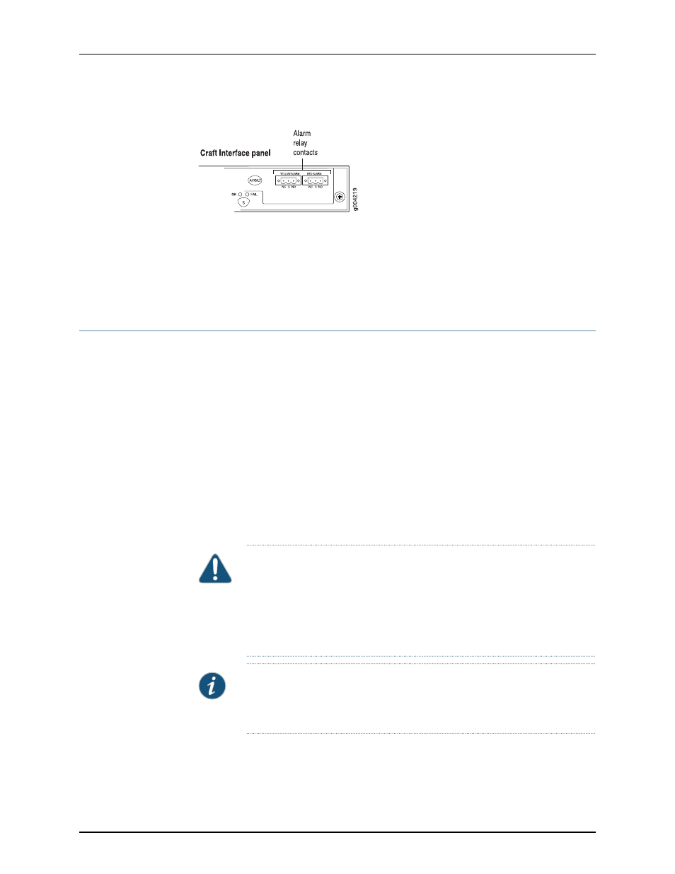
Figure 20: Alarm Relay Contacts
Related
Documentation
MX480 Craft Interface Description on page 37
•
•
Alarm LEDs and Alarm Cutoff/Lamp Test Button on the MX480 Craft Interface on
page 37
•
MX480 Component LEDs on the Craft Interface on page 38
MX480 Power Supply Overview
•
MX480 Power System Description on page 41
•
MX480 AC Power Supply Description on page 42
•
MX480 AC Power Supply LEDs on page 44
•
MX480 DC Power Supply Description on page 44
•
MX480 DC Power Supply LEDs on page 46
MX480 Power System Description
The MX480 router uses either AC or DC power supplies. The MX480 router is configurable
with two, three, or four AC power supplies or two or four DC power supplies. The power
supplies connect to the midplane, which distributes the different output voltages produced
by the power supplies to the router components, depending on their voltage requirements.
Each power supply is cooled by its own internal cooling system.
CAUTION:
The router cannot be powered from AC and DC power supplies
simultaneously. The first type of power supply detected by the router when
initially powered on determines the type of power supply allowed by the
router. All installed power supplies of the other type are disabled by the router.
If you install a power supply of the other type while the router is operating,
the router disables the power supply and generates an alarm.
NOTE:
Routers configured with DC power supplies are shipped with a blank
panel installed over the power distribution modules. Routers configured with
AC power supplies have no blank panel.
Related
Documentation
MX480 AC Power Supply Description on page 42
•
•
MX480 DC Power Supply Description on page 44
41
Copyright © 2013, Juniper Networks, Inc.
Chapter 2: MX480 Hardware Components