Juniper Networks SRX 210 User Manual
Page 161
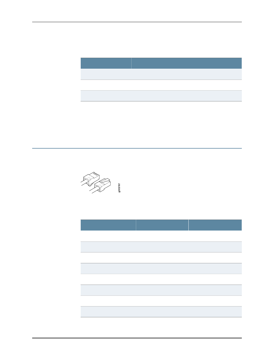
Table 45: RJ-45 Connector Pinouts for the Services Gateway Ethernet
Port (1 Gbps) (continued)
Signal
Pin
BI_DB-
6
BI_DD+
7
BI_DD-
8
Related
Documentation
Interface Cable and Wire Specifications for the SRX210 Services Gateway on page 143
•
•
RJ-45 Connector Pinouts for the SRX210 Services Gateway Console Port on page 145
•
RJ-45 Connector Pinouts for the SRX210 Services Gateway Console Port
shows the RJ-45 connector pinouts for the console port.
Figure 28: Console Cable Connector
describes the RJ-45 connector pinouts for the console port.
Table 46: RJ-45 Connector Pinouts for the Services Gateway Console
Port
Description
Signal
Pin
Request to Send
RTS
1
Data Terminal Ready
DTR
2
Transmit Data
TXD
3
Signal Ground
Ground
4
Signal Ground
Ground
5
Receive Data
RXD
6
Data Set Ready
DSR/DCD
7
Clear to Send
CTS
8
145
Copyright © 2013, Juniper Networks, Inc.
Appendix C: SRX210 Services Gateway Interface Cable Specifications and Connector Pinouts