Chapter 2 installation, 1 hardware description, 1 switch front panel – PLANET WGSW-52040 User Manual
Page 25: 2 led indications, Chapter 2 installation -1, Ardware, Escription, 1 switch front panel -1, 2 led indications -1, 1 hardware description 2.1.1 switch front panel
Chapter 2 INSTALLATION
This section describes how to install your Managed Switch and make connections to the Managed Switch.
Please read the following topics and perform the procedures in the order being presented. To install your
Managed Switch on a desktop or shelf, simply complete the following steps.
In this paragraph, we will describe how to install the Managed Switch and the installation points attended to
it.
2.1 Hardware Description
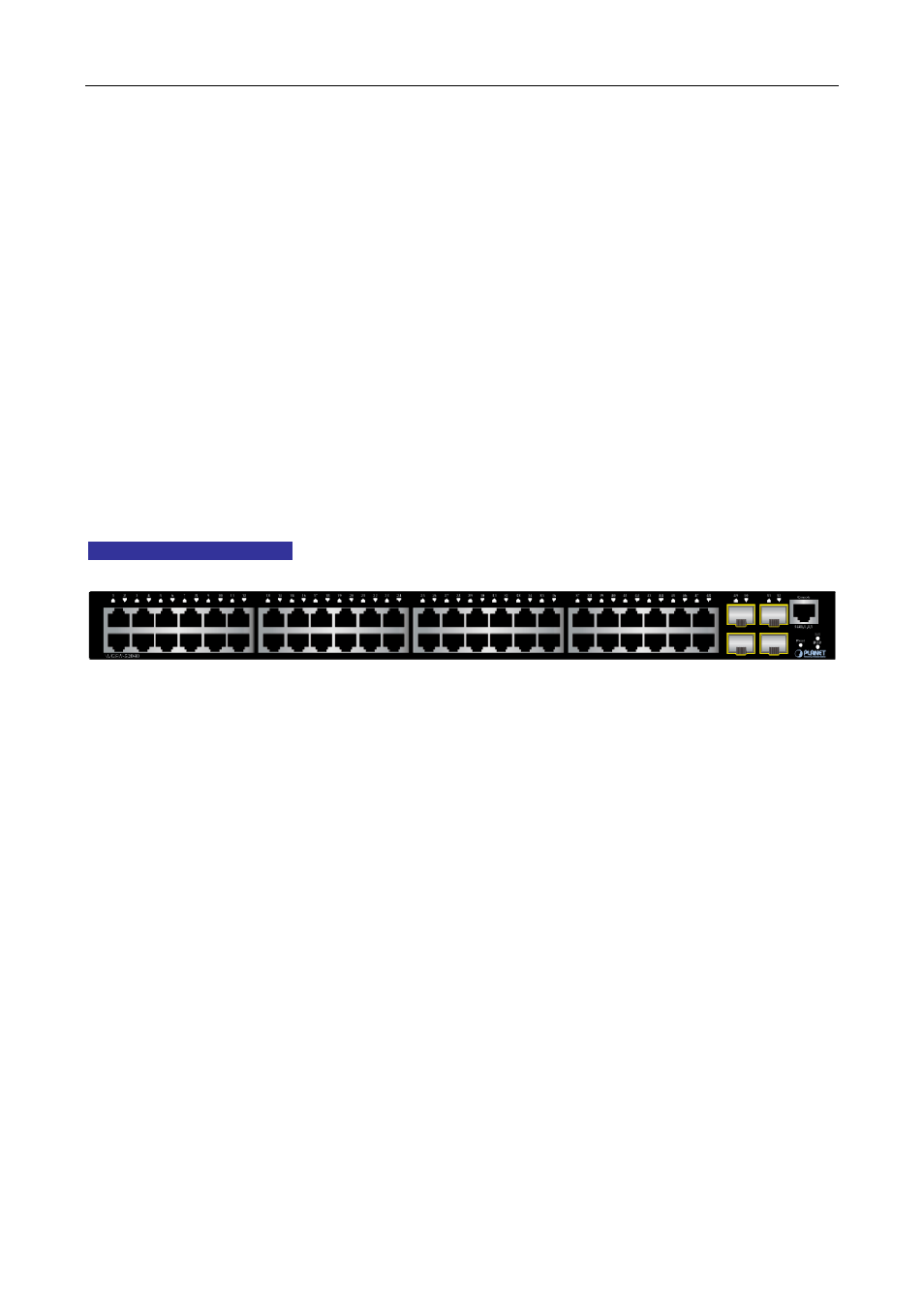
2.1.1 Switch Front Panel
The unit front panel provides a simple interface monitoring the switch.
Figure 2-1
shows the front panel of the
Managed Switch.
WGSW-52040 Front Panel
Figure 2-1 WGSW-52040 front panel
■
Gigabit TP interface
10/100/1000Base-T Copper, RJ-45 Twist-Pair: Up to 100 meters.
■
Gigabit SFP slots
100/1000Base-X mini-GBIC slot, SFP (Small Form Factor Pluggable) transceiver module: From 550
meters (Multi-mode fiber), up to 10/20/30/40/50/70/120 kilometers (Single-mode fiber).
■
Console Port
The console port is a RJ-45 port connector. It is an interface for connecting a terminal directly. Through
the console port, it provides rich diagnostic information including IP Address setting, factory reset, port
management, link status and system setting. Users can use the attached DB9 to RJ-45 console cable in
the package and connect to the console port on the device. After the connection, users can run any
terminal emulation program (Hyper Terminal, ProComm Plus, Telix, Winterm and so on) to enter the
startup screen of the device.
■
Reset button
On the front panel, the reset button is designed for rebooting the Managed Switch without turning off and on
the power.
2.1.2 LED Indications
2-1