HEIDENHAIN TNC 620 (34056x-04) Cycle programming User Manual
Page 234

Fixed Cycles: Multipass Milling
10.4
FACE MILLING (Cycle 232, DIN/ISO: G232, software option 19)
10
234
TNC 620 | User's Manual Cycle Programming | 5/2013
Maximum plunging depth Q202 (incremental
value):
Maximum
amount that the tool is advanced
each time. The TNC calculates the actual plunging
depth from the difference between the end point
and starting point of the tool axis (taking the
finishing allowance into account), so that uniform
plunging depths are used each time. Input range 0
to 99999.9999
Allowance for floor Q369 (incremental):
Distance used for the last infeed. Input range 0 to
99999.9999
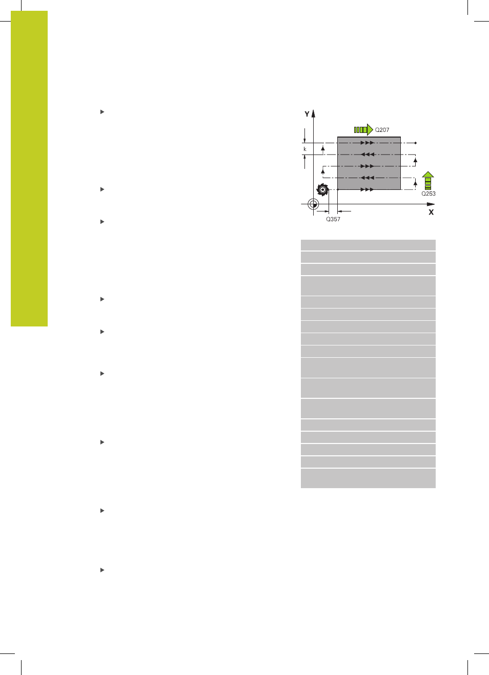
Max. path overlap factor Q370:
Maximum
stepover factor k. The TNC calculates the actual
stepover from the second side length (Q219) and
the tool radius so that a constant stepover is used
for machining. If you have entered a radius R2
in the tool table (e.g. tooth radius when using a
face-milling cutter), the TNC reduces the stepover
accordingly. Input range 0.1 to 1.9999
Feed rate for milling Q207: Traversing speed of
the tool in mm/min while milling. Input range 0 to
99999.999 alternatively
FAUTO, FU, FZ
Feed rate for finishing Q385: Traversing speed of
the tool in mm/min, while milling the last infeed.
Input range 0 to 99999.9999; alternatively
FAUTO,
FU, FZ
Feed rate for pre-positioning Q253: Traversing
speed of the tool in mm/min when approaching
the starting position and when moving to the next
pass. If you are moving the tool transversely to
the material (Q389=1), the TNC moves the tool
at the feed rate for milling Q207. Input range 0 to
99999.9999, alternatively
FMAX, FAUTO
Set-up clearance Q200 (incremental): Distance
between tool tip and the starting position in the
tool axis. If you are milling with machining strategy
Q389=2, the TNC moves the tool at the set-up
clearance over the current plunging depth to the
starting point of the next pass. Input range 0 to
99999.9999
Clearance to side Q357 (incremental): Safety
clearance to the side of the workpiece when
the tool approaches the first plunging depth,
and distance at which the stepover occurs if the
machining strategy Q389=0 or Q389=2 is used.
Input range 0 to 99999.9999
2nd set-up clearance Q204 (incremental):
Coordinate in the spindle axis at which no collision
between tool and workpiece (fixtures) can occur.
Input range 0 to 99999.9999, alternatively
PREDEF
NC blocks
71 CYCL DEF 232 FACE MILLING
Q389=2
;STRATEGY
Q225=+10
;STARTNG PNT 1ST AXIS
Q226=+12
;STARTNG PNT 2ND
AXIS
Q227=+2.5
;STARTNG PNT 3RD AXIS
Q386=-3
;END POINT 3RD AXIS
Q218=150
;FIRST SIDE LENGTH
Q219=75
;2ND SIDE LENGTH
Q202=2
;MAX. PLUNGING DEPTH
Q369=0.5
;ALLOWANCE FOR
FLOOR
Q370=1
;MAX. TOOL PATH
OVERLAP
Q207=500
;FEED RATE FOR
MILLING
Q385=800
;FINISHING FEED RATE
Q253=2000
;F PRE-POSITIONING
Q200=2
;SET-UP CLEARANCE
Q357=2
;CLEARANCE TO SIDE
Q204=2
;2ND SET-UP
CLEARANCE
