Cycle run – HEIDENHAIN TNC 620 (34056x-04) Cycle programming User Manual
Page 231
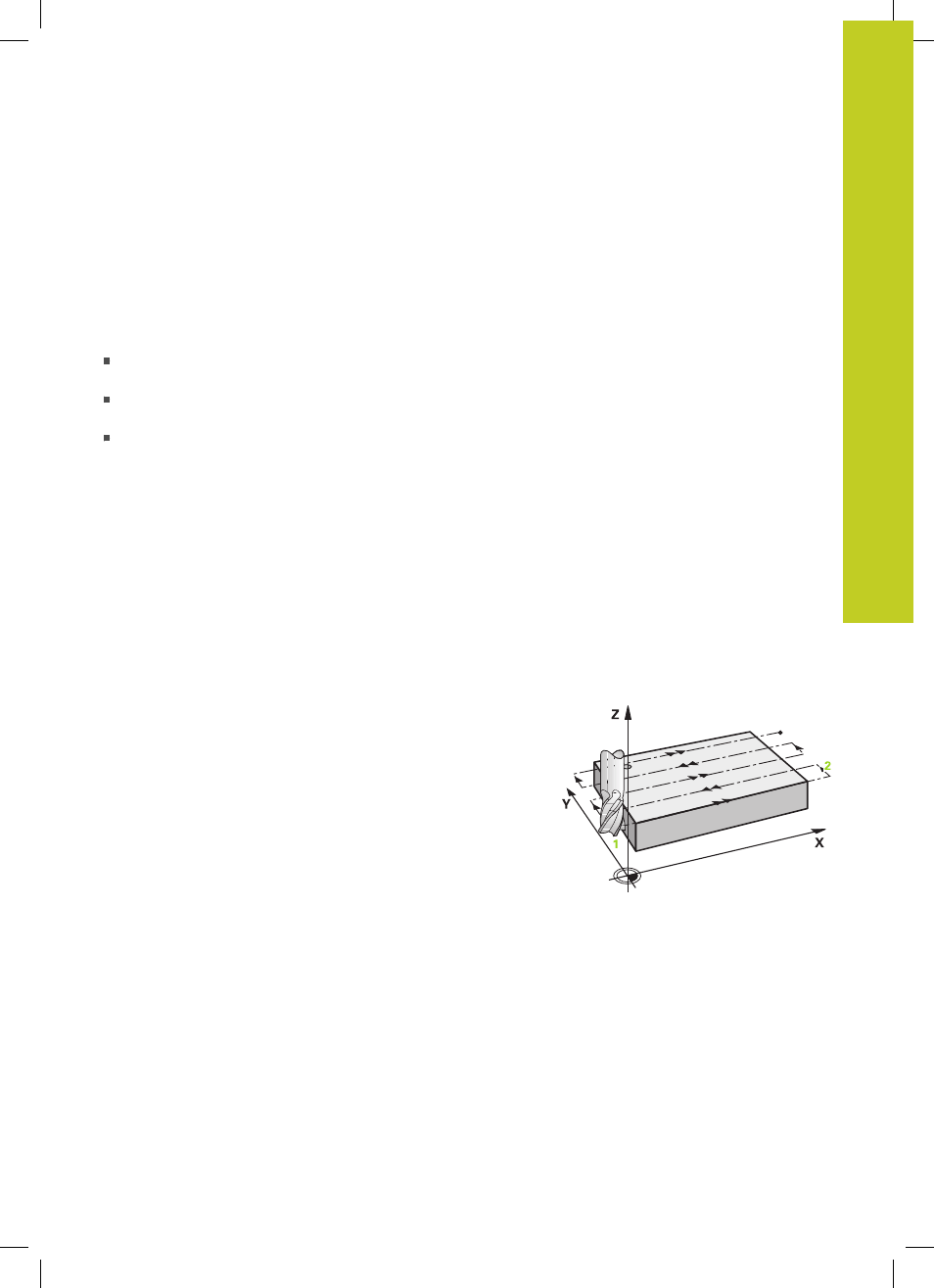
FACE MILLING (Cycle 232, DIN/ISO: G232, software option 19)
10.4
10
TNC 620 | User's Manual Cycle Programming | 5/2013
231
10.4
FACE MILLING (Cycle 232, DIN/ISO:
G232, software option 19)
Cycle run
Cycle 232 is used to face mill a level surface in multiple infeeds
while taking the finishing allowance into account. Three machining
strategies are available:
Strategy Q389=0
: Meander machining, stepover outside the
surface being machined
Strategy Q389=1:
Meander machining, stepover within the
surface being machined
Strategy Q389=2:
Line-by-line machining, retraction and
stepover at the positioning feed rate
1 From the current position, the TNC positions the tool at rapid
traverse
FMAX to the starting position using positioning logic
1
: If the current position in the spindle axis is greater than the
2nd set-up clearance, the control positions the tool first in the
machining plane and then in the spindle axis. Otherwise it first
moves to the 2nd set-up clearance and then in the machining
plane. The starting point in the machining plane is offset from
the edge of the workpiece by the tool radius and the safety
clearance to the side.
2 The tool then moves in the spindle axis at the positioning feed
rate to the first plunging depth calculated by the control.
Strategy Q389=0
3 The tool subsequently advances to the stopping point
2
at the
programmed feed rate for milling. The end point lies
outside
the surface. The control calculates the end point from the
programmed starting point, the programmed length, the
programmed safety clearance to the side and the tool radius.
4 The TNC offsets the tool to the starting point in the next pass
at the pre-positioning feed rate. The offset is calculated from
the programmed width, the tool radius and the maximum path
overlap factor.
5 The tool then moves back in the direction of the starting point
1
.
6 The process is repeated until the programmed surface has been
completed. At the end of the last pass, the tool plunges to the
next machining depth.
7 In order to avoid non-productive motions, the surface is then
machined in reverse direction.
8 The process is repeated until all infeeds have been machined. In
the last infeed, simply the finishing allowance entered is milled
at the finishing feed rate.
9 At the end of the cycle, the tool is retracted in
FMAX to the 2nd
set-up clearance.