Figure 49, Equation 3 – Basler Electric BE1-11m User Manual
Page 83
9424200996 Rev L
71
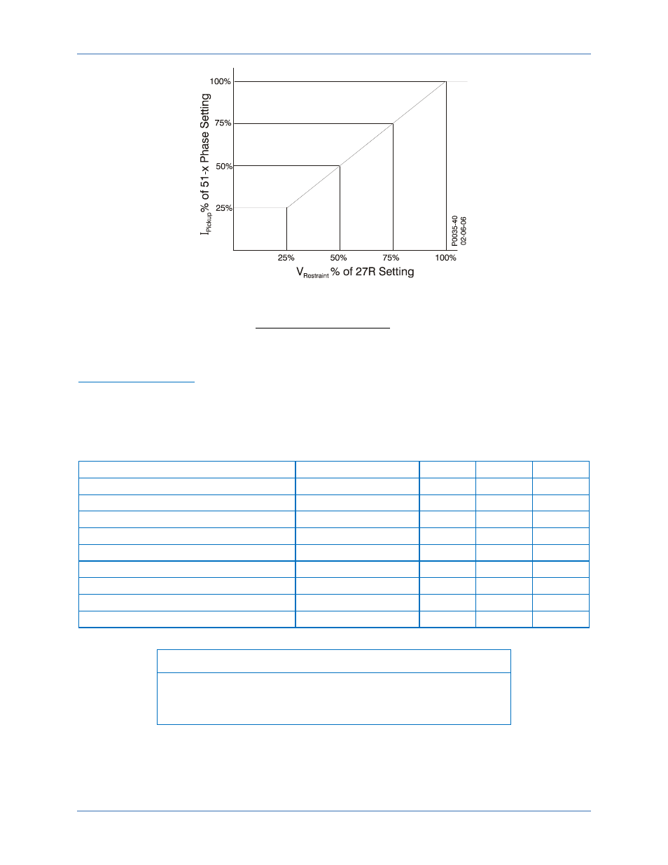
Figure 49. 51 Phase Pickup Level Compensation
𝐴𝑐𝑡𝑢𝑎𝑙 𝑃𝑖𝑐𝑘𝑢𝑝 𝐿𝑒𝑣𝑒𝑙 =
𝑆𝑒𝑛𝑠𝑖𝑛𝑔 𝑉𝑜𝑙𝑡𝑎𝑔𝑒 𝐿𝑒𝑣𝑒𝑙
𝑅𝑒𝑠𝑡𝑟𝑎𝑖𝑛𝑡 𝑃𝑖𝑐𝑘𝑢𝑝 𝑆𝑒𝑡𝑡𝑖𝑛𝑔 × 51 𝑃ℎ𝑎𝑠𝑒 𝑃𝑖𝑐𝑘𝑢𝑝 𝑆𝑒𝑡𝑡𝑖𝑛𝑔
Equation 3. Restraint Pickup Level
Phase VT Configuration
The 51/27R function can be set to monitor either Vpp or Vpn depending upon the Phase VT Connection
settings. See the
chapter for details on how to set the phase VT connections. Table 24
shows which voltage measurements are used by each 51 element for each possible phase VT connection
and 51/27 voltage monitoring mode setting.
Table 24. Phase VT Connection Cross Reference
Phase VT Connection
51/27 Mode
51A
51B
51C
4W
Vpp
Vab
Vbc
Vca
4W
Vpn
Van
Vbn
Vcn
3W
Vpp
Vab
Vbc
Vca
AN
Vpn
Van
n/a
n/a
BN
Vpn
n/a
Vbn
n/a
CN
Vpn
n/a
n/a
Vcn
AB
Vpp
Vab
n/a
n/a
BC
Vpp
n/a
Vbc
n/a
CA
Vpp
n/a
n/a
Vca
Note
For single-phase sensing, the unmonitored phase is not restrained or
controlled. These phases are marked in the table by n/a (not
applicable).
When single-phase voltage sensing is used, only the inverse overcurrent element on the phase with
voltage magnitude information is affected by the 51/27R feature. Thus, in voltage control mode, the 51
elements on the two unmonitored phases will always be disabled. In voltage restraint mode, the 51
elements on the two unmonitored phases will not have their overcurrent pickup settings adjusted from
100%.
BE1-11m
Inverse Overcurrent (51) Protection