Operational settings, Table 19 – Basler Electric BE1-11m User Manual
Page 73
9424200996 Rev L
61
Table 19. Logic Inputs and Outputs
Name
Logic Function
Purpose
Block
Input
Disables the 50 function when true
Trip
Output
True when the 50 element is in a trip condition
Pickup
Output
True when the 50 element is in a pickup condition
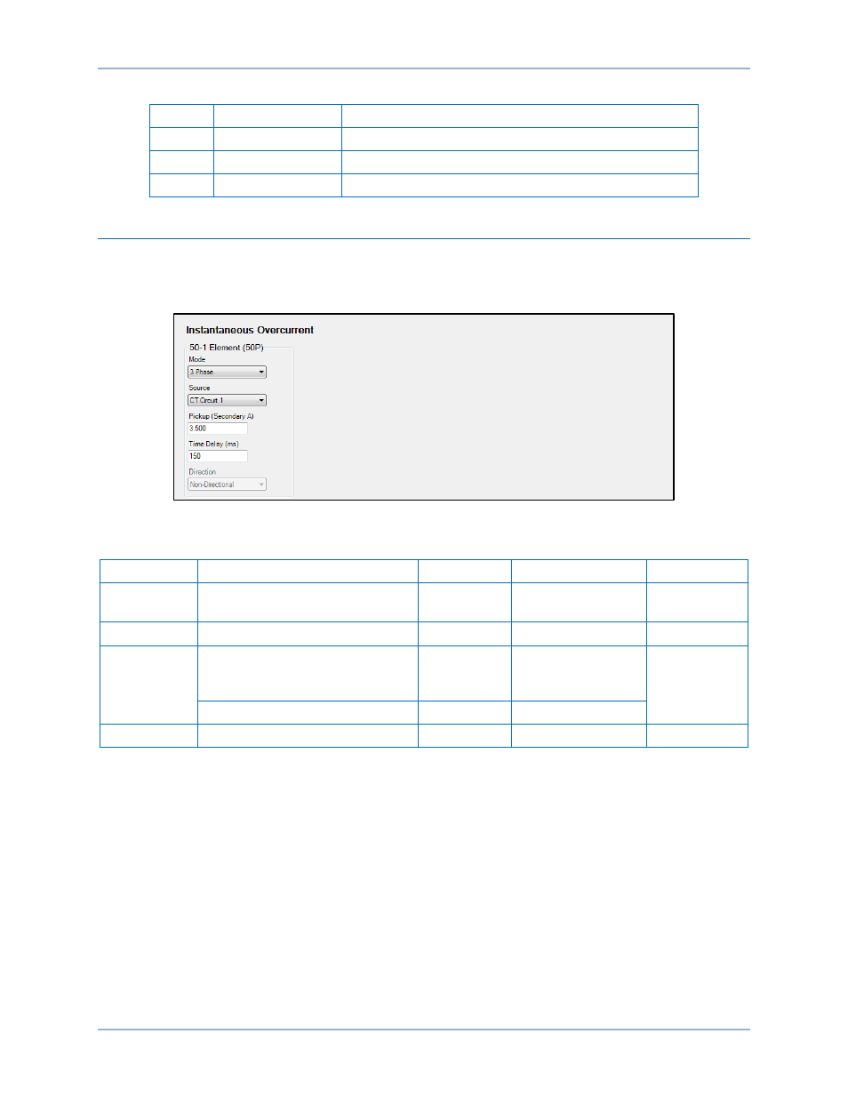
Operational Settings
Instantaneous overcurrent element operational settings are configured on the Instantaneous Overcurrent
(50) settings screen (Figure 45) in BESTCOMSPlus. Setting ranges and defaults are summarized in
Table 20.
Figure 45. Instantaneous Overcurrent Settings Screen
Table 20. Operational Settings
Setting
Range
Increment
Unit of Measure
Default
Mode
Disabled, IA, IB, IC, 3 Phase,
3I0, I1, I2, IG, or Unbalance
n/a
n/a
Disabled
Source
*
CT Circuit 1 or CT Circuit 2
n/a
n/a
CT Circuit 1
Pickup
0 or 0.5 to 150 (5A CTs)
0 or 0.1 to 30 (1A CTs)
0 or 0.01 to 7.5 (SEF)
varies
amps
0
2 to 100 (Unbalance mode)
1
percent
Time Delay
0 to 60,000
varies
milliseconds
0
* For protection systems equipped with two sets of CTs.
BE1-11m
Instantaneous Overcurrent (50) Protection