Figure 357, Remote rtd, Module – Basler Electric BE1-11m User Manual
Page 542
530
9424200996 Rev L
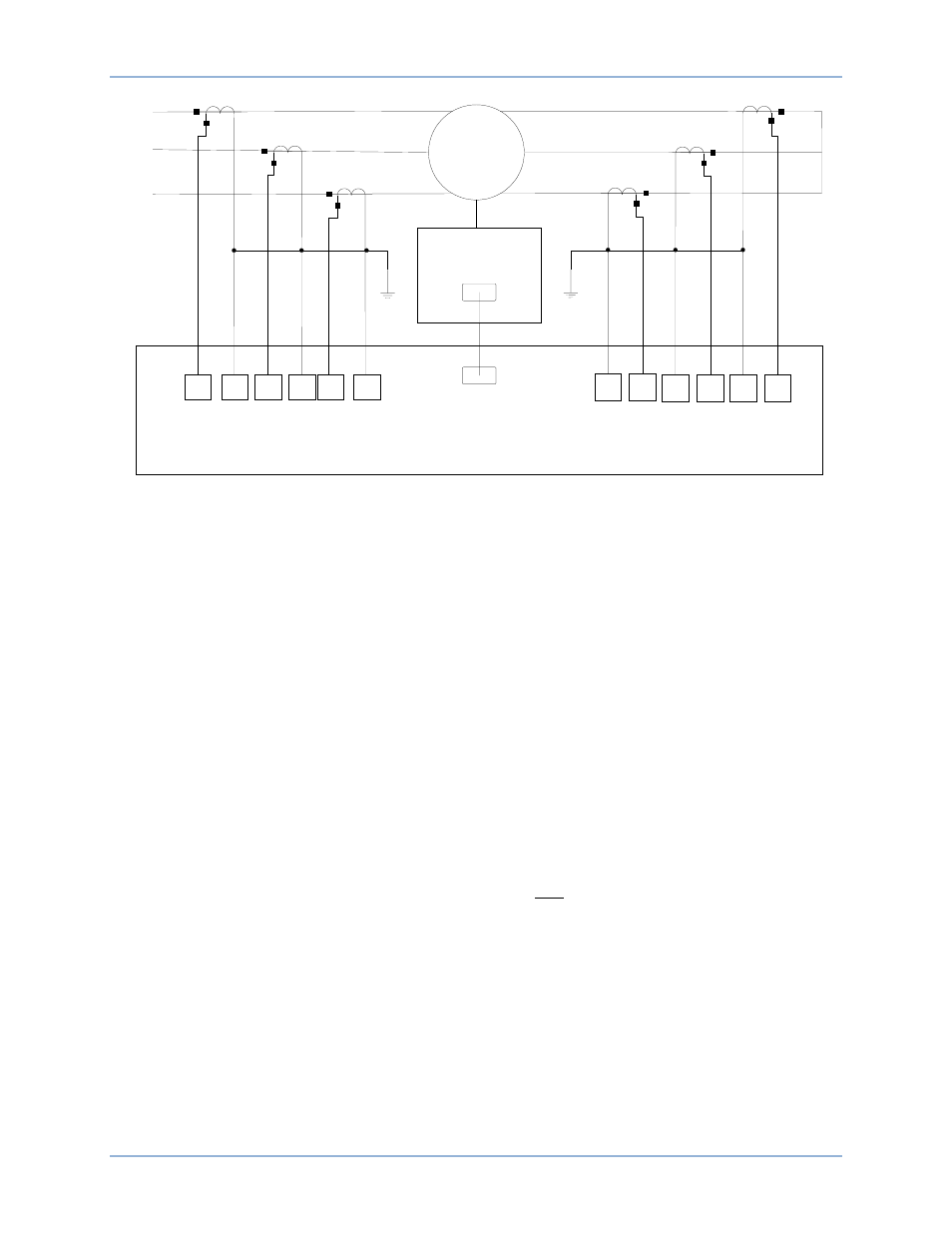
Figure 357. Motor Differential Connection Example
CT Circuit 1 Tap and CT Circuit 2 Tap are shown here, but calculated from the System Parameters,
Sensing Transformers screen (Figure 342). With equal CT ratios, the secondary currents through the
BE1-11m restraint algorithm for external faults and load are similar, and the operating current is very
small. If the differential CTs do not match, use the TAP settings on the System Parameters, Sensing
Transformers screen to balance the differential.
Running Slope
In running mode, the differential can be more sensitive, yet provide security and reliability at 15% as
described by IEEE C37.96-2000, IEEE Guide for AC Motor Protection. Set the Restraint Slope 1 %
setting to 15.
Starting Slope
The BE1-11m considers the motor to be starting when current is greater than 2
• FLA in any phase. The
starting mode ends when current in all three phases drops below 2
• FLA. Therefore, the 2
nd
Slope Pickup
(starting) should be set at the point that restraint current is 2
• FLA where motor torques and heating
settle quickly to running mode currents (as observed in typical time-current curves). With Restraint Slope
1 % (running) set to 15%, Iop for Restraint Slope 2 pickup should be 15 percent of restraint current. See
Equation 50.
2𝑛𝑑 𝑆𝑙𝑜𝑝𝑒 𝑃𝑖𝑐𝑘𝑢𝑝 𝐶𝑢𝑟𝑟𝑒𝑛𝑡 = 𝐹𝐿𝐴
𝑆𝑒𝑐𝑜𝑛𝑑𝑎𝑟𝑦
∙ 2 = 4.54 ∙ 2 = 9.08
2𝑛𝑑 𝑆𝑙𝑜𝑝𝑒 𝑃𝑖𝑐𝑘𝑢𝑝 𝑆𝑒𝑡𝑡𝑖𝑛𝑔 =
9.08
2.0 = 4.54
Equation 50. 2
nd
Slope (Starting) Pickup Setting
Figure 358 shows an example of 2
nd
Slope Restrained Operation.
Based upon good engineering practices during starting mode to overcome dc offset and CT mismatches,
set Restraint Slope 2 % at 1.7 times the running mode slope and add a 25 percent margin. Restraint
Slope 2 % is calculated using Equation 51.
𝑅𝑒𝑠𝑡𝑟𝑎𝑖𝑛𝑡 𝑆𝑙𝑜𝑝𝑒 2 % = 1.7 ∙ 1.25 ∙ 15% = 32%
Equation 51. Restraint Slope 2 %
Set the 2
nd
Slope Pickup (starting) at 4.54 and the Restraint Slope 2 % at 32.
M
A
1
I
A
1
•
A
2
I
A
1
A
3
I
B
1
•
A
4
I
B
1
A
5
I
C
1
•
A
6
I
C
1
B
5
I
C
1
•
B
6
I
C
1
B
1
I
A
2
•
B
2
I
A
2
B
3
I
B
2
•
B
4
I
B
2
Remote RTD
Module
BE
1
-
11
m
/
6
Stator RTDs
/
2
Bearing RTDs
/
1
Ambient RTDs
RJ
-
45
RJ
-
45
A
B
C
Settings Calculation Examples
BE1-11m